Warsaw, Poland, May 28, 2026
From Chaos to Control: the new topology standard for AI Data Centers
As AI transitions from episodic training runs to persistent, revenue-generating inference, workloads are expected to redistribute from a limited number of centralized facilities to a broader network of regional and edge-adjacent deployments. This change fundamentally alters how capacity must be planned, deployed, and expanded over time. Cooling infrastructure, once treated as a secondary engineering concern, is now becoming a defining constraint at AI scale.
Traditional direct liquid cooling architectures involved distributed in-row CDU units placed within the white space, with separate cooling loops assigned to each row. While effective at lower power densities, this approach became limited as AI rack densities increased to 60-100 kW and clusters grew beyond 10 MW. The white space started filling with cooling equipment instead of computing hardware, and hundreds of small pumps, filters, and connections added operational complexity, increased leak risk, and made maintenance more difficult.
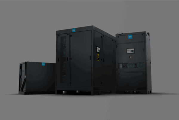
Modern AI workloads require a different approach: one based on centralization, designed from the outset for scale and continuous expansion. Instead of deploying dozens or hundreds of in-row CDUs, the new topology centers on one or two high-capacity FDUs, typically in the 5 MW class, located outside the white space in a dedicated gray area. This architecture reduces the number of cooling loops, simplifies the hydraulic layout, and frees valuable rack space for IT equipment, while providing a clear, centralized point of control and maintenance. This topology is engineered and deployed by DCX Liquid Cooling Systems, where cooling is treated not as an auxiliary function but as a scalable, industrial-grade system.
Why Traditional Topologies Fail the AI Era
Traditional Direct Liquid Cooling topologies were engineered under the assumption that incremental capacity could be delivered by deploying two in-row CDUs per row, yielding roughly 1 MW of cooling per pair. This model was adequate for earlier generations of compute hardware but does not meet the demands of modern AI racks exceeding 100 kW per rack
One of the most illustrative examples of how cooling infrastructure directly affects the stability of critical digital systems was the outage at a data center supporting the Chicago Mercantile Exchange (CME), operated by CyrusOne in the Chicago region. The incident led to a temporary suspension of derivatives trading after the Globex electronic trading platform was taken offline, immediately disrupting financial markets across North America, Europe, and Asia. According to Reuters and Data Center Dynamics, the immediate cause was a chiller plant failure affecting multiple chillers, demonstrating how partial loss of thermal control can force protective shutdowns in large-scale facilities.
This failure mode underscores the inherent fragility of low-temperature, chiller-dependent cooling architectures. In contrast approach proposed by DCX Poland is designed to operate at elevated secondary loop inlet temperatures of 40-45 °C, enabling extensive use of dry coolers and significantly reducing reliance on mechanical chillers as critical points of failure.
At an industry level, such incidents highlight a broader structural issue: distributed CDU layouts, with cooling complexity embedded within the white space, struggle to scale to AI-era densities. As power per rack increases, the white space becomes congested with cooling hardware at the expense of compute capacity, while maintenance and expansion introduce disproportionate operational risk. These practical limitations of legacy topologies are driving a transition toward architectures that centralize hydraulic systems outside the compute zone, enabling more scalable, efficient, and maintainable cooling for AI data centers.
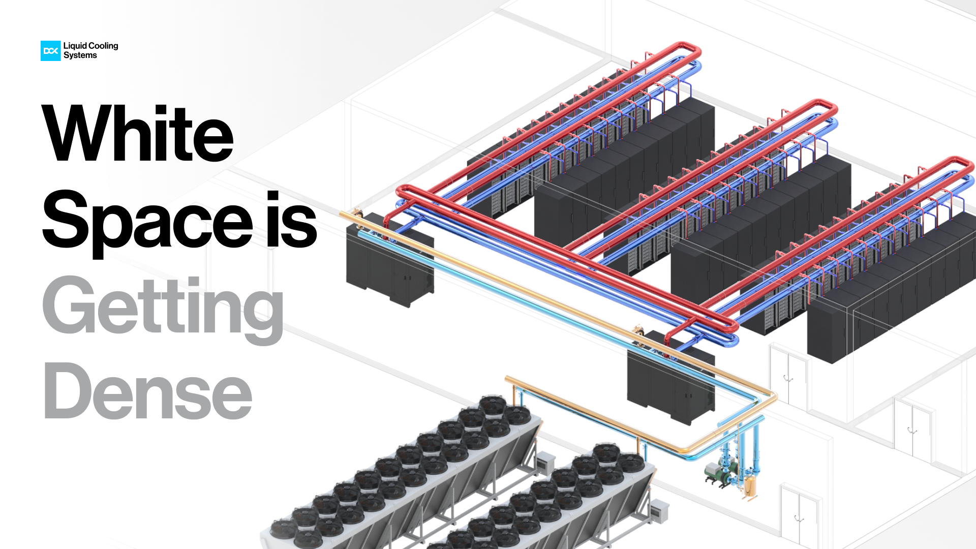
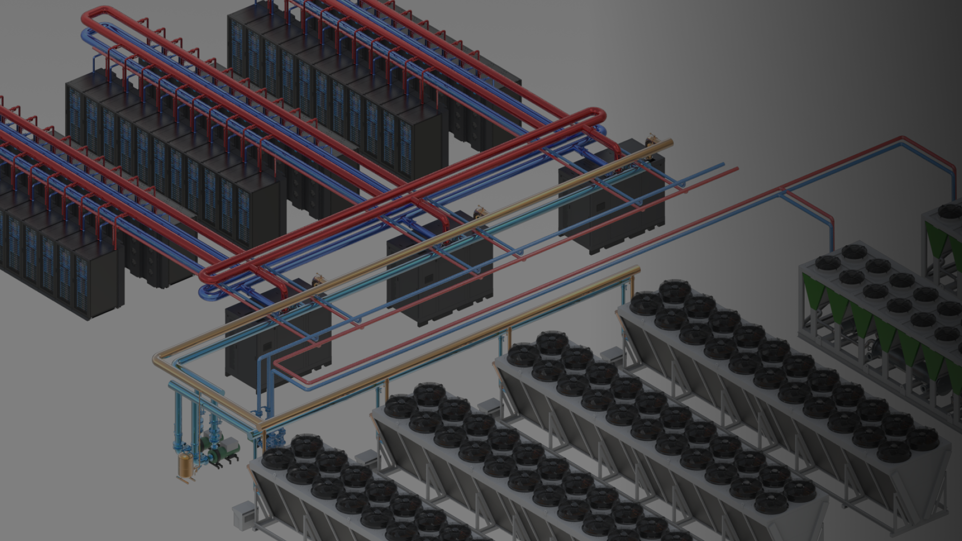
Figure 1. The new topology standard for modern data centers
Supply Chain Constraints Are Redefining Data Center Topology
The shift toward centralized, FDU-based data center topology is being accelerated not only by rising AI power densities, but also by persistent supply chain and delivery constraints across the industry. According to recent market data, more than half of data center projects experienced delays of three months or longer in 2025, despite stabilization in global equipment lead times. Average delivery timelines for critical infrastructure components remain significantly elevated compared to pre 2020 levels, while the construction of a 50 MW facility now typically spans 18 months, with key materials often ordered up to 24 months in advance.
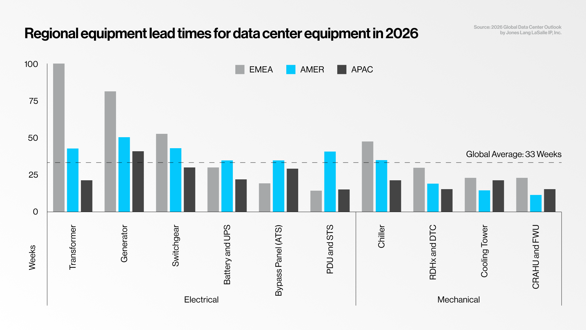
Figure 2. Regional equipment lead times for data center equipment in 2026
In this environment, highly distributed cooling architectures, reliant on large numbers of rack-level or in-row devices, expose projects to greater logistical risk and integration delays. Centralized FDU-based topology reduces the total number of critical components, simplifies procurement, and enables earlier infrastructure standardization, allowing developers to decouple core cooling capacity from rack-level deployment schedules. As operators increasingly maintain strategic inventories of key components to mitigate supply uncertainty, architectures built around repeatable, high-capacity FDUs offer a more resilient and schedule-aligned foundation for delivering AI data centers at scale.
AI-Ready Topology: Separation by Design
An AI-ready topology introduces a clear separation between the compute zone and the cooling infrastructure. Instead of populating the white space with dozens of small CDU units and their associated pumps, valves, and control systems, the entire hydraulic complexity is relocated to the grey space. As a result, the white space becomes a compute-focused environment with significantly fewer active mechanical components. In practice, this reduces the number of hydraulic connections at the rack level, minimizes potential leak points, and creates more stable mechanical conditions directly at the servers.
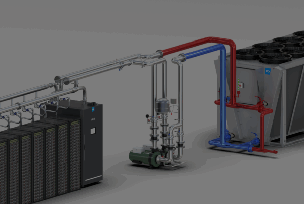
From a hydraulic perspective, the key change is the centralization of coolant distribution in high-capacity FDUs. A single FDU can supply multiple server rows, replacing hundreds of small, independent loops with a limited number of large, efficient circuits. By relocating pumps, filters, valves, and redundancy to the Grey Space, maintenance can be performed without entering the compute area, shortening service windows and reducing operational risk.
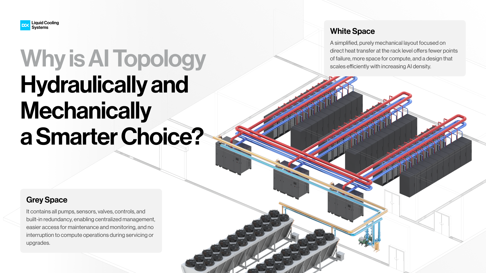
Figure 3. Why is AI Topology hydraulically and mechanically a smarter choice
AI Topology Explained
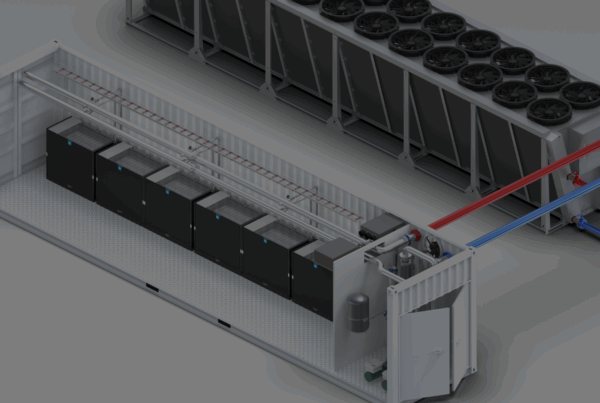
Modern AI-ready data center topology fundamentally departs from the legacy model of distributed, rack-adjacent CDUs by relocating liquid-cooling infrastructure into centralized, high-capacity FDUs positioned outside the white space. In this architecture, one or two large-scale FDUs, each capable of delivering up to 5 MW of cooling capacity, are deployed in a dedicated grey space and supply the entire data hall through a centralized secondary cooling loop.
From a system-engineering perspective, the topology is inherently simpler and more scalable: capacity growth is achieved by adding another modular FDU block rather than multiplying dozens of small CDU units alongside racks. Centralization also reduces operational risk and maintenance complexity, fewer units mean fewer moving parts, fewer filters and pumps to service, and a substantially lower probability of failures occurring in proximity to critical IT equipment.
In addition, the centralized FDU-based topology is inherently aligned with Uptime Institute Tier III requirements, as redundancy is implemented at the component level, including pumps, heat exchangers, controls, and power supplies, rather than being distributed across dozens of small edge devices. By consolidating cooling generation into centralized cooling plants, the architecture enforces a clear physical and functional separation between mechanical systems and compute infrastructure, significantly improving operational safety, serviceability, and fault isolation.
Each FDU operates as a modular, scalable building block, delivering up to 5 MW of cooling capacity within a compact ~4 m² footprint, allowing data halls to scale linearly by adding identical units without redesigning the hydronic architecture. The higher available pump head enables the use of a single, extended Technology Cooling System (TCS) loop within the white space, replacing fragmented secondary loops with a unified distribution network. This simplified TCS piping acts as the hydronic backbone of the facility, engineered to minimize frictional losses, maintain stable flow conditions, and preserve high heat-transfer coefficients across long distances, critical for high-density AI racks.
By removing CDUs from the compute area, the topology also delivers tangible space retention benefits, freeing enough floor area to accommodate one or two additional racks per row. Combined, these characteristics result in a cooling infrastructure that is not only Tier III compliant but also mechanically robust, easier to maintain, and purpose-built for sustained multi-megawatt AI operations.
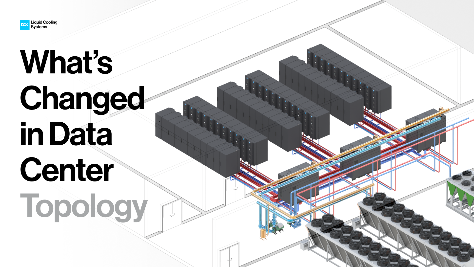
Figure 4. What’s changed in Data Center Topology
Why Centralized FDUs Are the New Standard
Looking toward the end of the decade, the transition to centralized, FDU-based cooling is not merely a response to higher rack densities, but a structural consequence of how AI workloads are reshaping the data center industry itself. According to the 2026 Global Data Center Outlook, artificial intelligence is expected to account for up to half of all data center workloads by 2030, with a pivotal shift anticipated around 2027 as inference overtakes training as the dominant driver of demand. Unlike episodic training runs, inference creates continuous, revenue-generating workloads that scale with user adoption and require geographically distributed, latency-sensitive infrastructure.
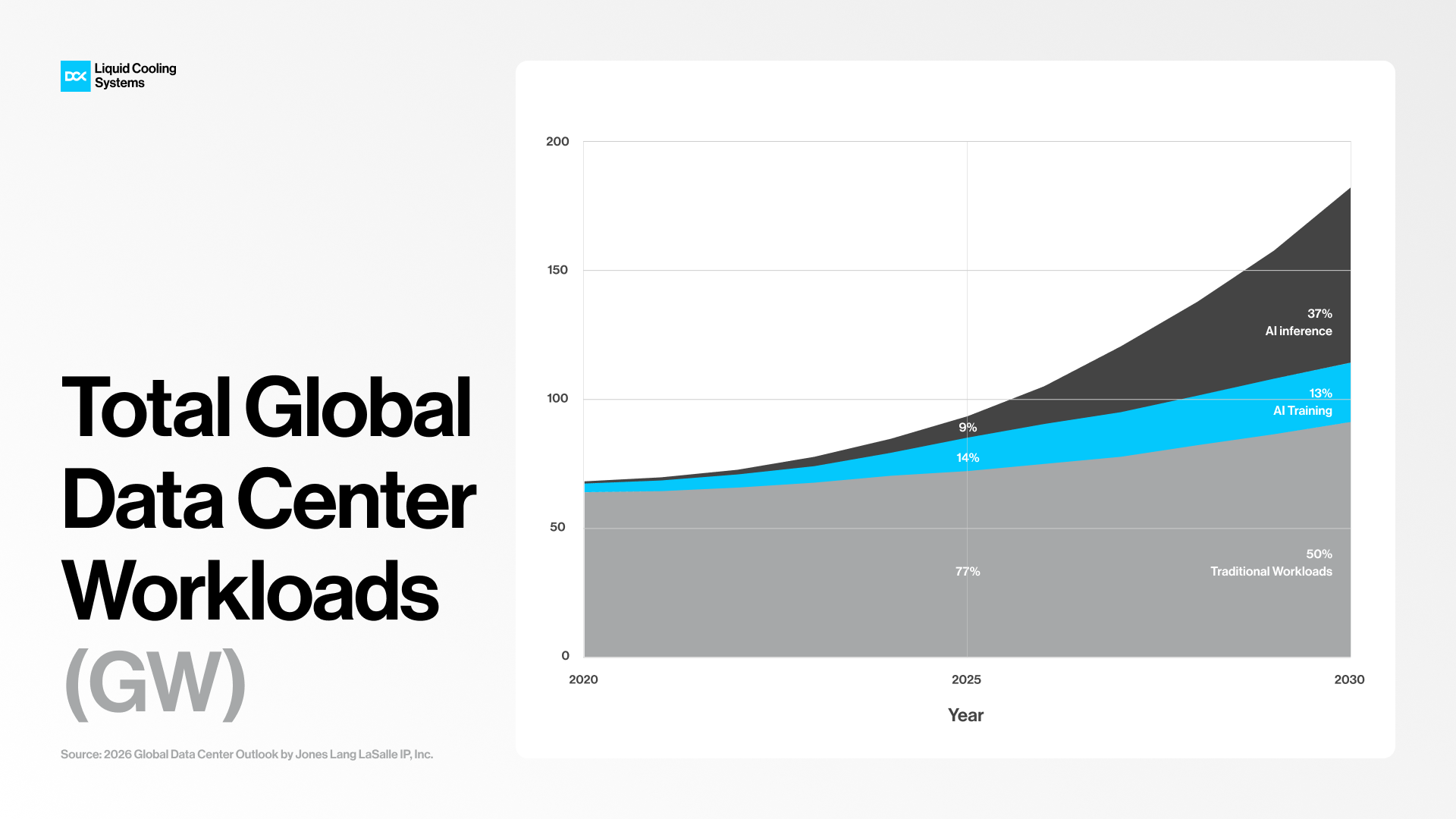
Figure 5. Projected shift in AI workload composition, with inference surpassing training after 2027
This shift favors modular, repeatable, and rapidly deployable data center designs, exactly the conditions under which centralized FDUs excel. By enabling predictable 5-15 MW expansion blocks, reducing operational complexity in the White Space, and supporting Tier-aligned redundancy at the system level, FDU-based topology aligns cooling infrastructure with the economic, geographic, and operational realities of the AI era. In this context, centralized FDUs are no longer an alternative architecture, they represent the cooling foundation required for the next phase of global AI infrastructure growth.
Source: Global Data Center Outlook 2026