
Warsaw, Poland, May 26, 2026
Direct-to-Chip Cooling: the precision technology behind the AI Data Center transformation
As demand for computing power continues to accelerate, the requirements placed on data center infrastructure are rising just as rapidly. The growth of AI-driven applications, high-performance computing, and increasingly dense server environments is reshaping the industry and making efficient, reliable liquid cooling a critical factor in ensuring performance, scalability, and operational resilience.
AI is turning data centers into dense, heat-limited machines. What used to be a "powerful server room" is now an industrial-scale compute plant where a single rack can dissipate tens of kilowatts continuously, and the bottleneck is no longer compute alone, but how efficiently you can remove heat. Air cooling can be pushed further with bigger fans and more airflow, but at high heat flux and rising rack densities, it runs into fundamental limits: noise, power, pressure drop, and diminishing thermal headroom.
That is why Direct-to-Chip cooling is moving from a niche optimization to a baseline engineering choice for AI infrastructure. Instead of cooling an entire rack volume indirectly, it delivers coolant to cold plates mounted on the primary heat sources: CPUs and GPUs, extracting heat by conduction and transporting it through a controlled liquid loop to a heat exchanger. The result is not just "better cooling," but a different thermal architecture: tighter junction-to-coolant temperature control, higher allowable rack density, and more predictable performance under sustained AI workloads.
What is Direct-to-Chip cooling?
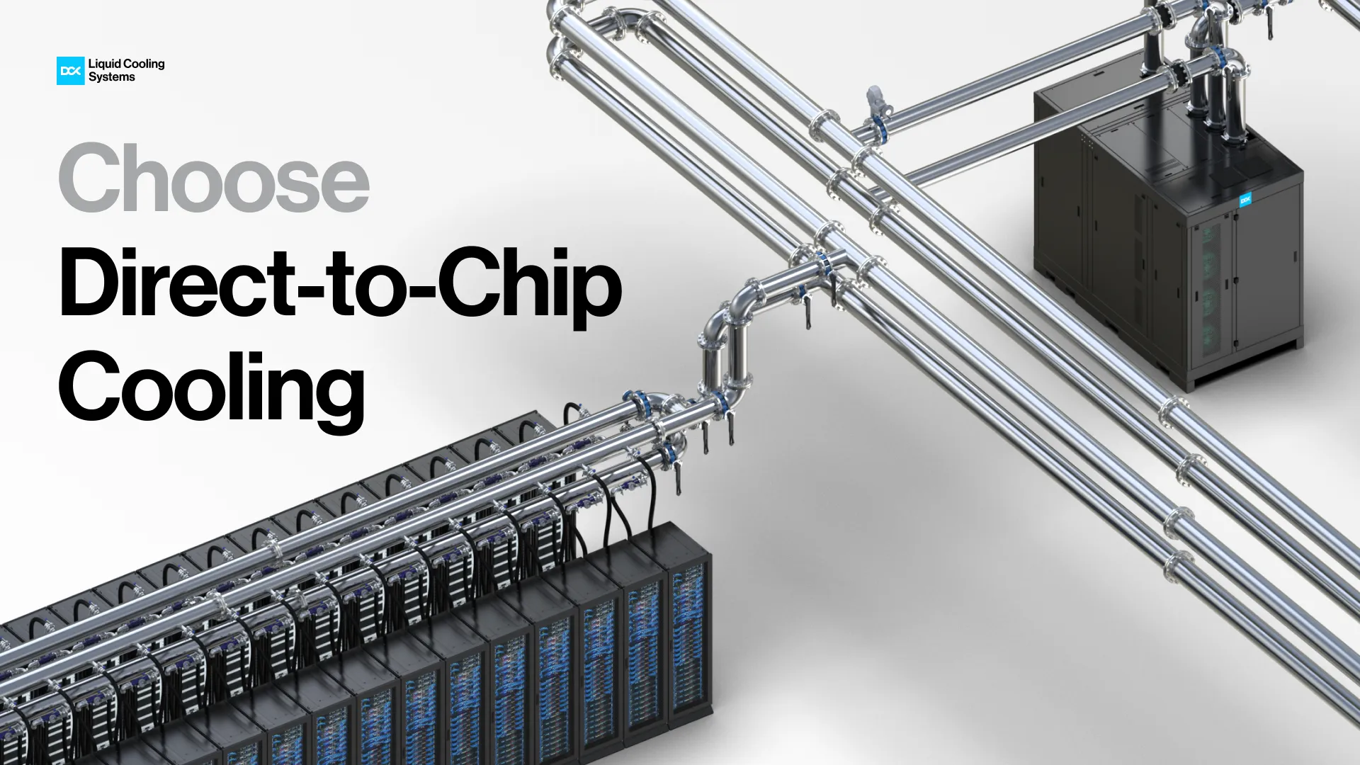
Direct-to-Chip cooling (DTC) is a liquid-cooling method in which heat is removed directly from electronic components by circulating a coolant through cold plates mounted on the hottest devices in a server, primarily CPUs and GPUs. These cold plates replace traditional air heat sinks and form a direct thermal interface with the chip packages, allowing heat to be transferred by conduction into the liquid flowing through internal channels.
The coolant, typically highly purified deionized water with corrosion inhibitors and chemical stabilizers, enters the cold plate through a supply manifold, absorbs heat as it passes over the components, and exits through a return manifold.
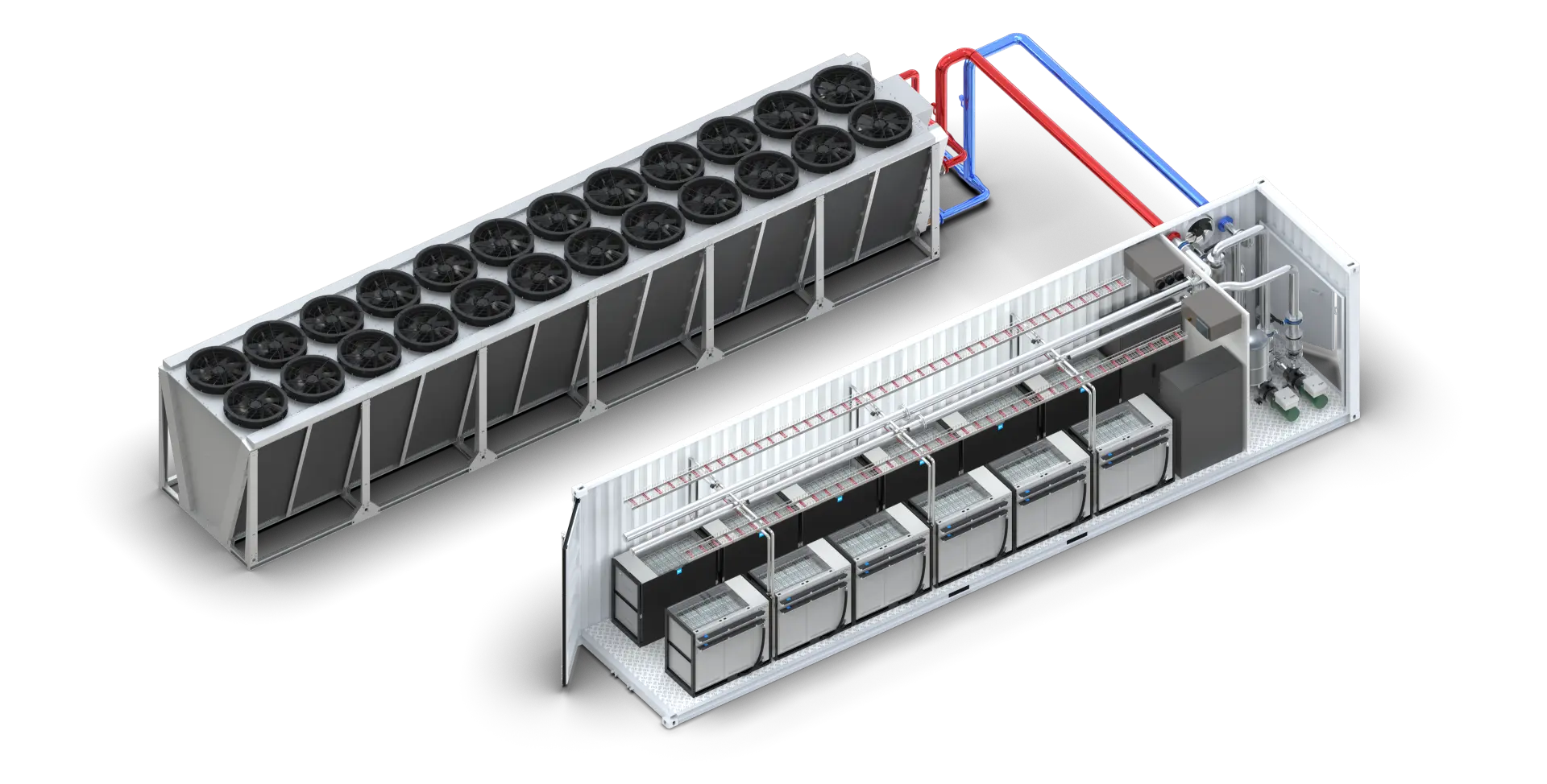
In addition to processors, cold plates may also cover other heat-generating elements on the server, such as memory modules, voltage-regulation components, or selected power electronics. The heated coolant is then transported via piping to a Coolant Distribution Unit (CDU), where a heat exchanger transfers the thermal energy from the technology cooling loop to the facility or primary cooling loop.
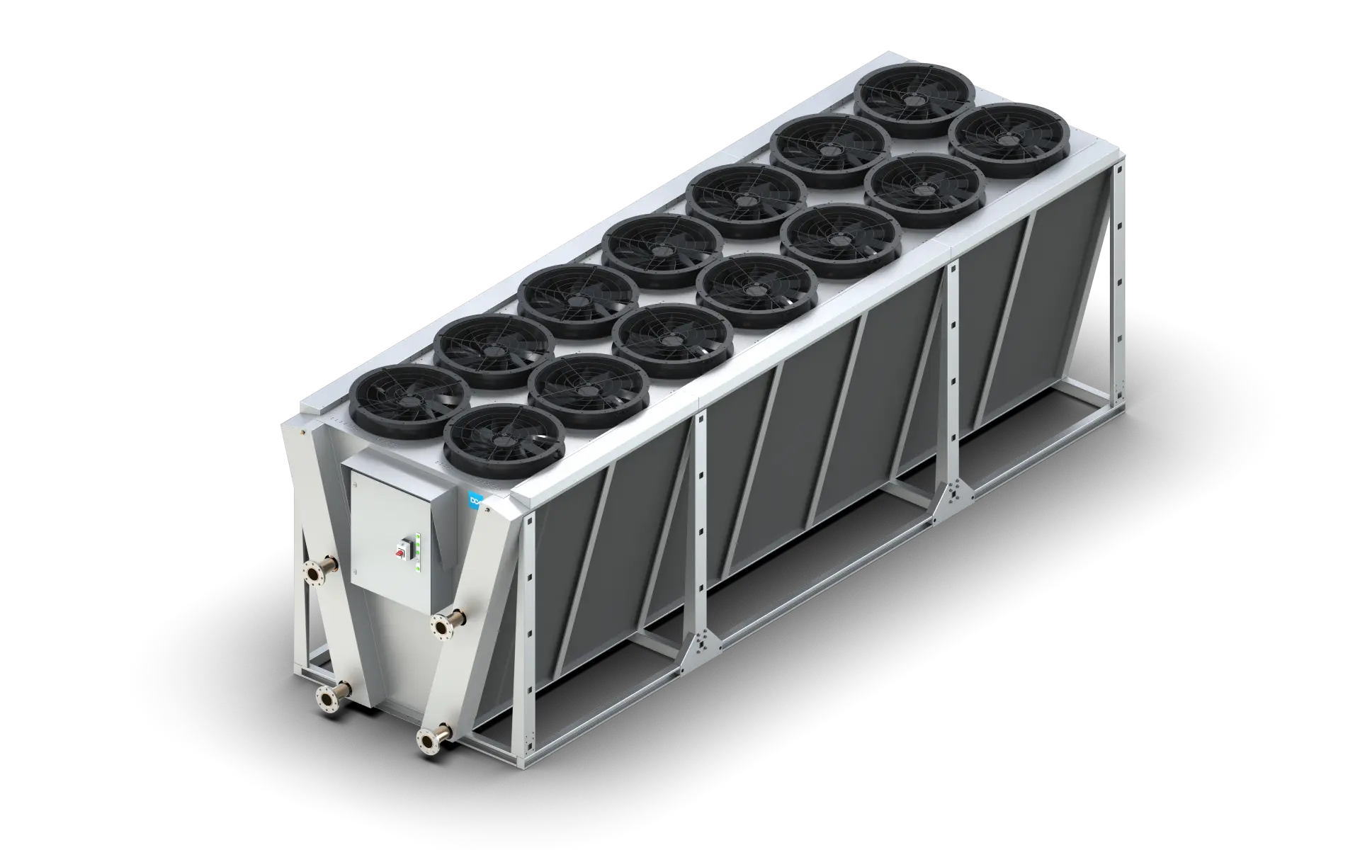
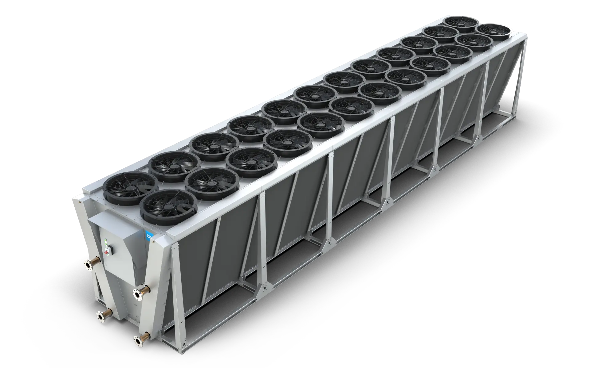
From there, the heat is ultimately rejected to the environment through systems such as dry coolers or cooling towers, or, if the return temperature is sufficiently high, reused for secondary applications such as space heating, industrial processes, or district heating networks.
With direct-to-chip cooling, it is typically possible to remove approximately 90% of the total heat generated within a rack, corresponding to the thermal load extracted directly from CPUs and GPUs via cold plates. The remaining 10%, commonly referred to as residual or "rest heat," originates from components that are not hydraulically connected to the liquid loop, including memory modules, power delivery components, networking devices, storage, and auxiliary electronics.
Consequently, a direct-to-chip deployment does not eliminate air-based heat rejection, it transforms the thermal architecture into a hybrid system. Effective integration of this residual heat path is therefore a critical design consideration, influencing rack layout, airflow management, facility water temperatures, and the overall cooling topology of AI-ready data centers.
The topology of a Direct-to-Chip cooling
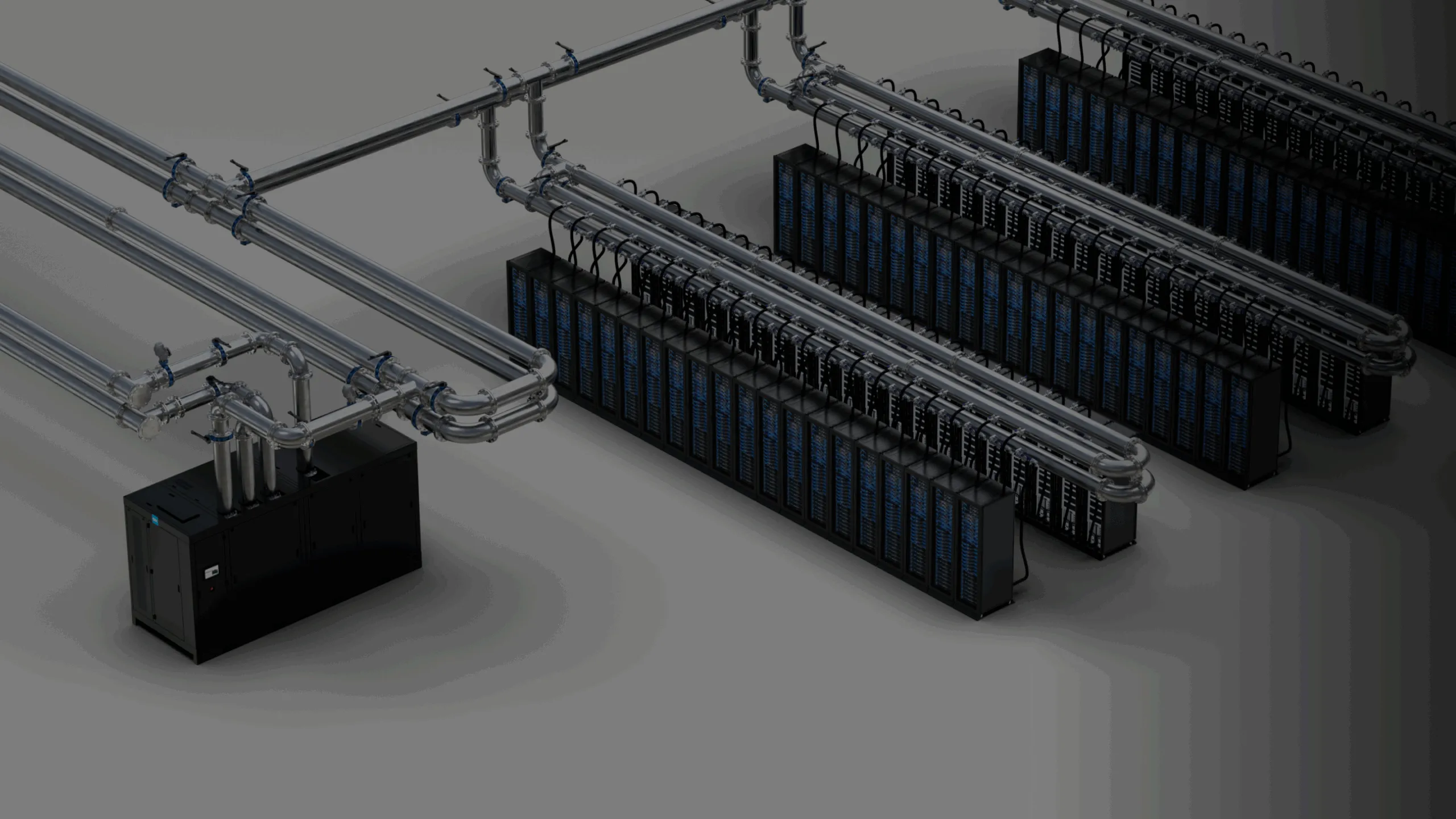
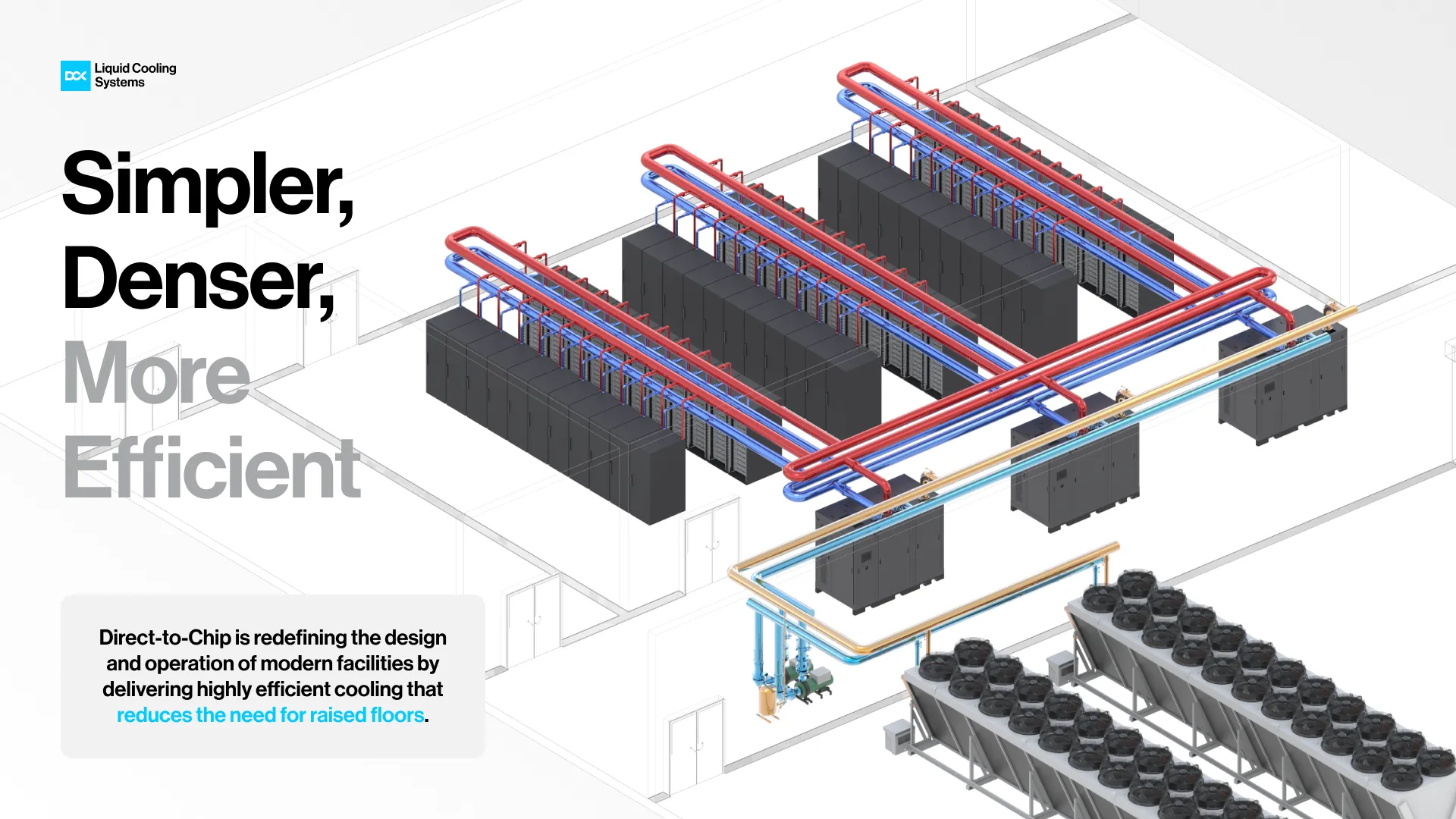
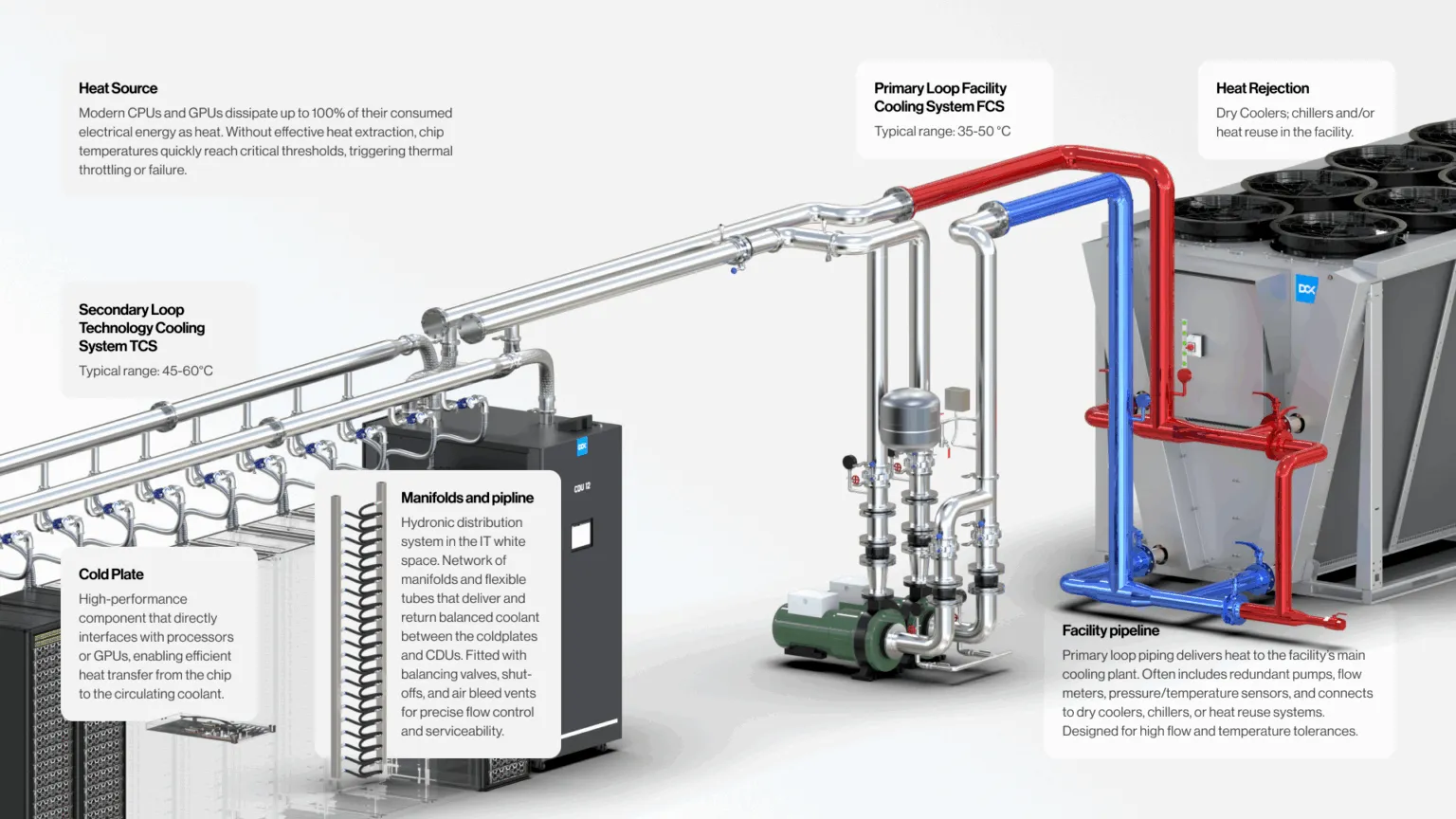
In a typical Direct-to-Chip cooling architecture, the topology is split into two clearly separated circuits: the Facility Cooling System (FCS) primary loop and the Technology Cooling System (TCS) secondary loop. This division has become a standard approach in modern AI data center and high-density data hall design, because it separates the "building-side" heat rejection infrastructure from the tightly controlled technology loop that directly serves CPU/GPU cold plates.
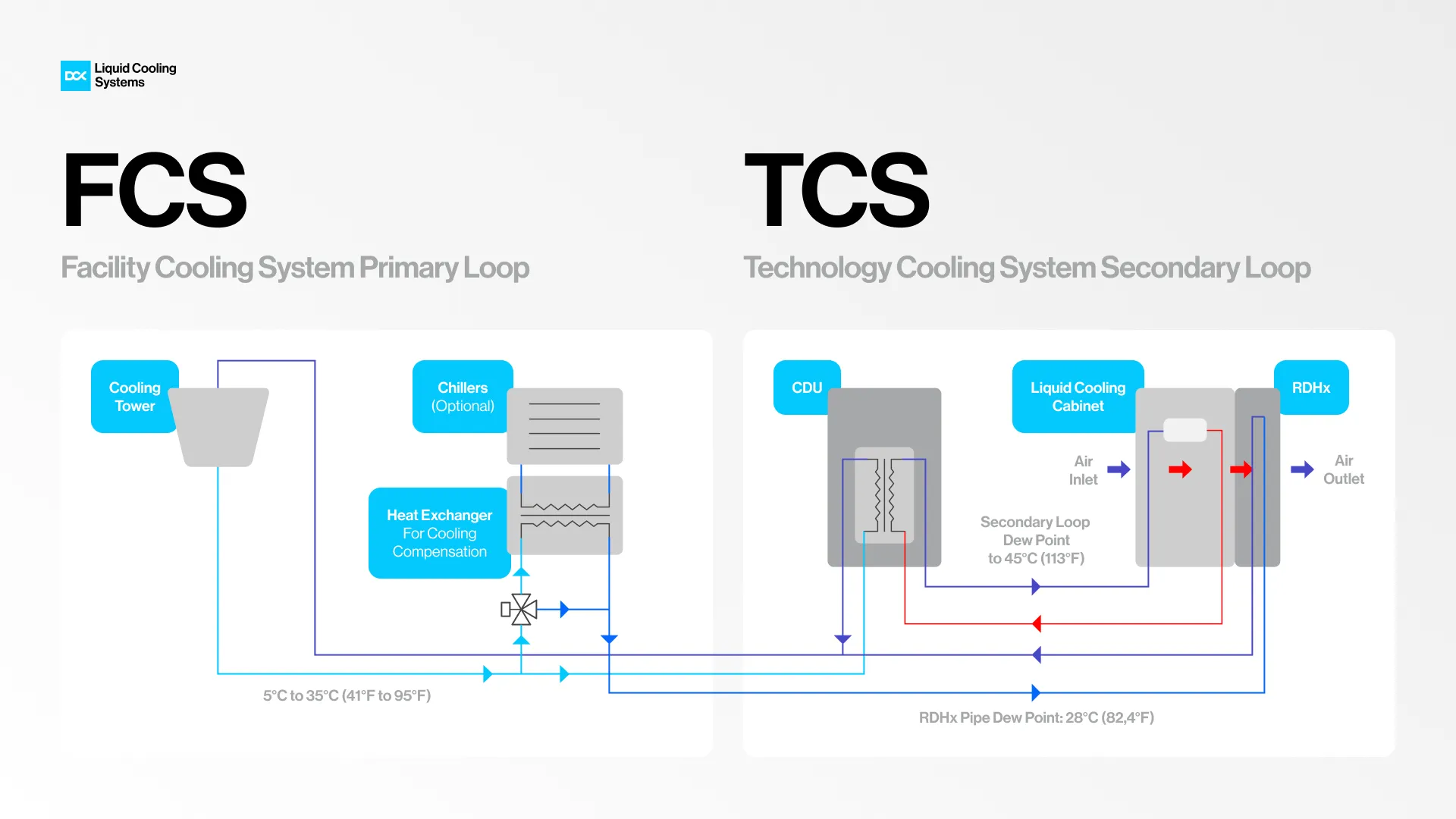
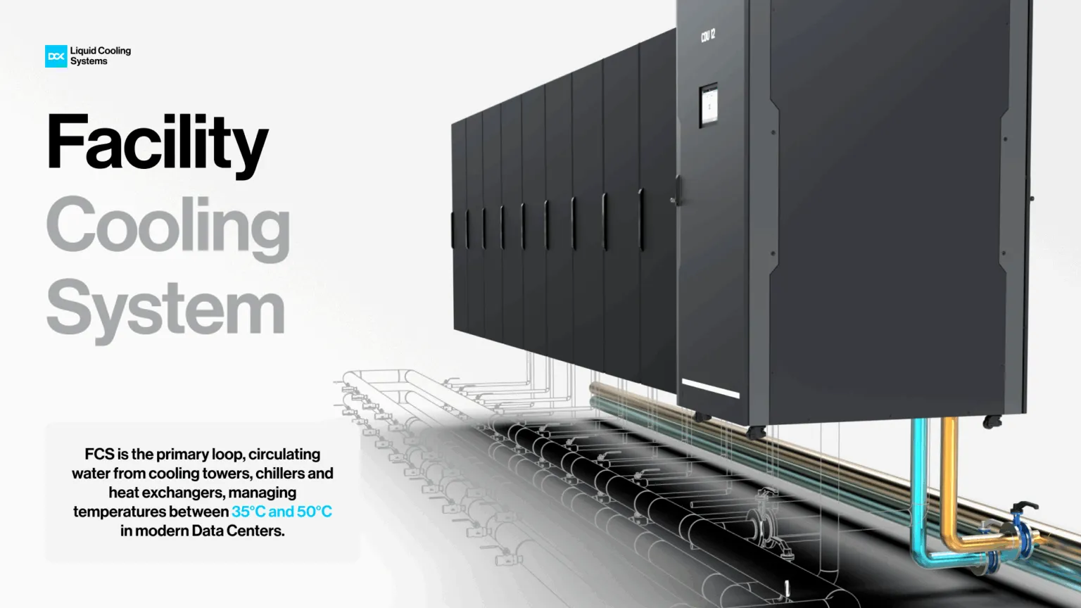
The primary loop (FCS) is the heat-rejection side. It includes heat rejection equipment such as dry coolers or cooling towers, and in some deployments also chillers. Facility water typically operates across a broad temperature range (e.g., 5-35°C), because its purpose is to efficiently reject thermal energy to ambient or to upstream cooling plant components. The critical interface between FCS and TCS is the heat exchanger, which hydraulically and chemically isolates the technology loop from facility water. This improves operational stability and reduces risk on the IT side.
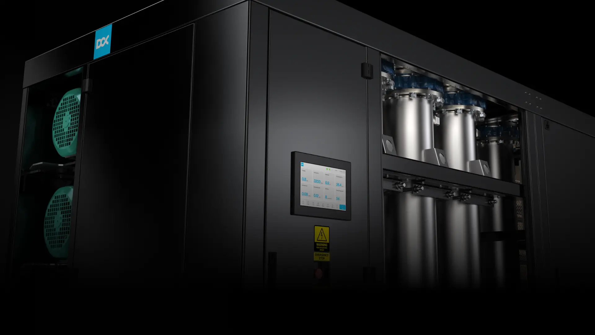
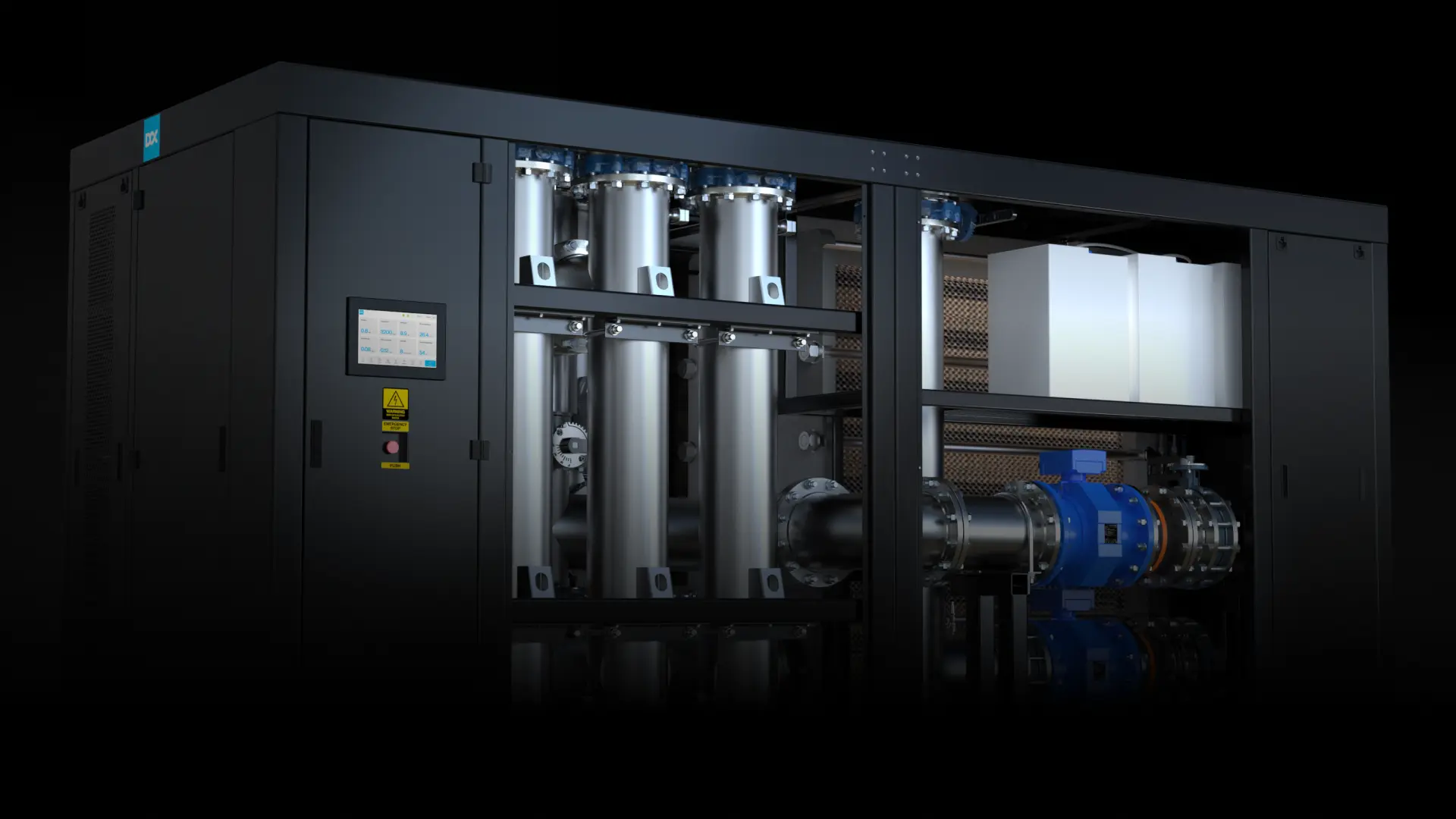
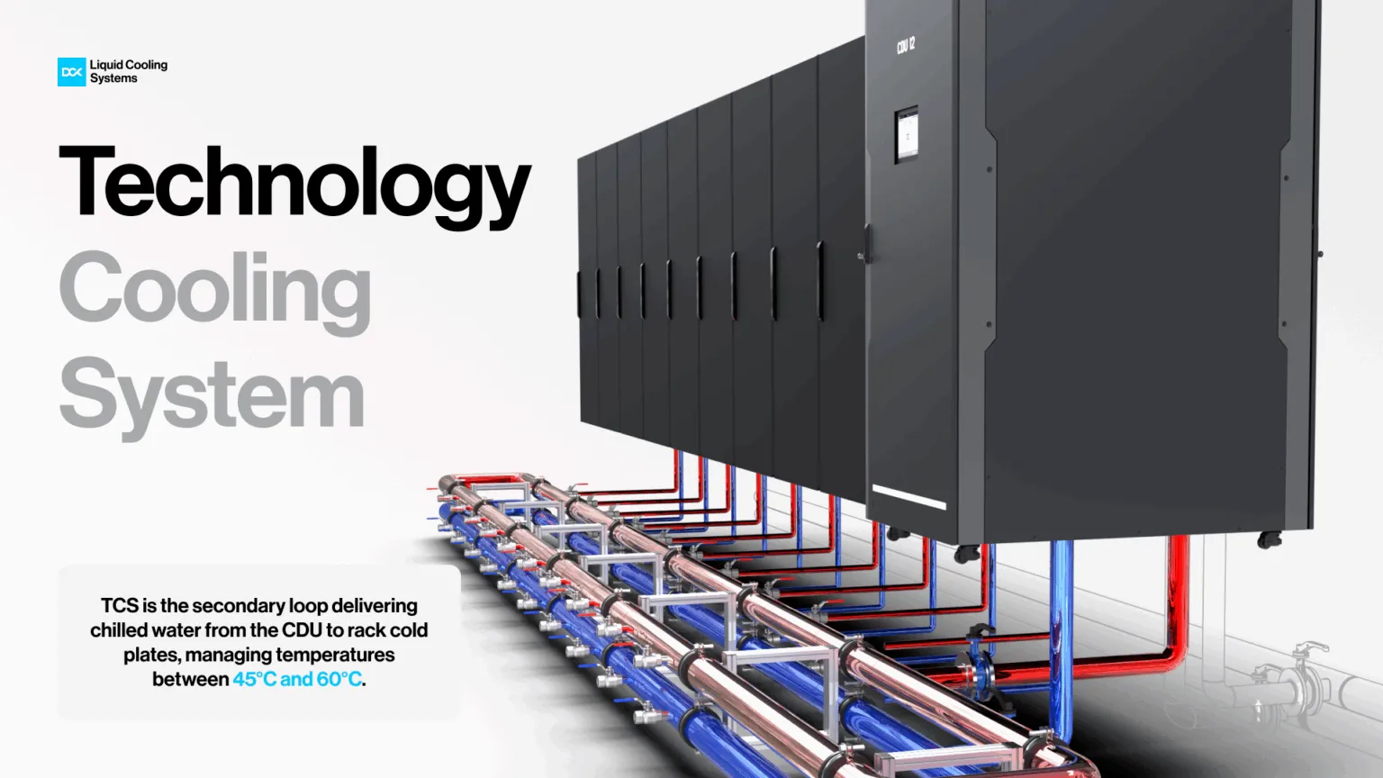
The secondary loop (TCS) is the actual technology cooling circuit for IT. It contains the CDU (Coolant Distribution Unit), distribution piping to the racks, manifolds, and the direct-to-chip cold plates mounted on the processors. This is the most critical part of the topology, because it operates in proximity to servers and must maintain precise coolant parameters: temperature, flow, and pressure, required by AI GPU clusters. The CDU acts as the heart of the system: it regulates rack-level flow rates, stabilizes supply/return temperatures, and typically integrates a heat exchanger and redundant pumps, since reliability in this loop directly determines the availability of the compute infrastructure.
The biggest challenges of Direct-to-Chip cooling
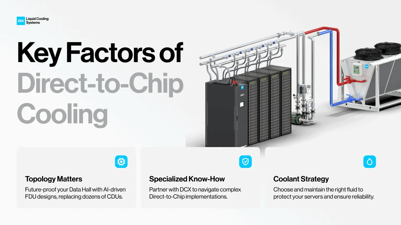
One of the biggest challenges of direct-to-chip cooling is choosing the right data center topology upfront, because the topology you lock in today will determine whether the facility remains scalable when rack densities move from 40-60 kW to 80-120 kW and beyond. It's not only about adding more cooling capacity: it's about designing a hydraulic architecture that is future-proof, serviceable, and expandable without rebuilding distribution, redundancy, or control layers.
The second challenge is organizational rather than purely technical: who actually owns the design and implementation responsibility. Direct liquid cooling is not a "learn-as-you-go" upgrade. The learning curve is expensive, and in practice, the end user pays for it through delays, rework, and availability risk. Successful deployments typically rely on experienced partners who can engineer the system end-to-end hydraulics, controls, commissioning, and take accountability for performance in an AI-ready data center environment.
The third and often most underestimated challenge is coolant and fluid management. Coolant selection, cleanliness, filtration strategy, corrosion control, compatibility with materials and seals, and long-term monitoring are critical to protecting high-value servers. In Direct-to-chip, the cooling loop runs directly next to compute, failures are not abstract they can become immediate operational risk. That's why coolant management and protection of IT equipment is frequently the most important challenge in real-world direct-to-chip operations, even more than topology and implementation itself.
The most critical components of Direct-to-chip cooling
In a Direct-to-Chip (DTC) cooling system, critical components are not limited to hardware. Just as important is the cooling medium chemistry, because in liquid cooling for AI data centers, the fluid becomes an active part of reliability engineering. A robust DTC design is therefore a combination of precision mechanical components, hydraulic topology, controls, and disciplined coolant management.
At the rack and server level, the most critical elements are the components that sit closest to the compute: rack manifolds, quick couplings, tubing, and the cold plates mounted directly on CPUs/GPUs. Pipe material selection is often underestimated, yet it is decisive for long-term reliability. The combination of elevated temperature and pressure requirements, plus the need for absolute tightness and corrosion-free operation, can make metallic piping an unsuitable choice in some liquid-cooling implementations.
At the facility level, DTC relies on multiple interconnected piping domains: the Technology Cooling System (TCS) as the secondary loop feeding racks, the Facility Water System (FWS) as the primary heat-rejection side, and often a separate cold-water circuit for heat exchangers (depending on how the plant is engineered).
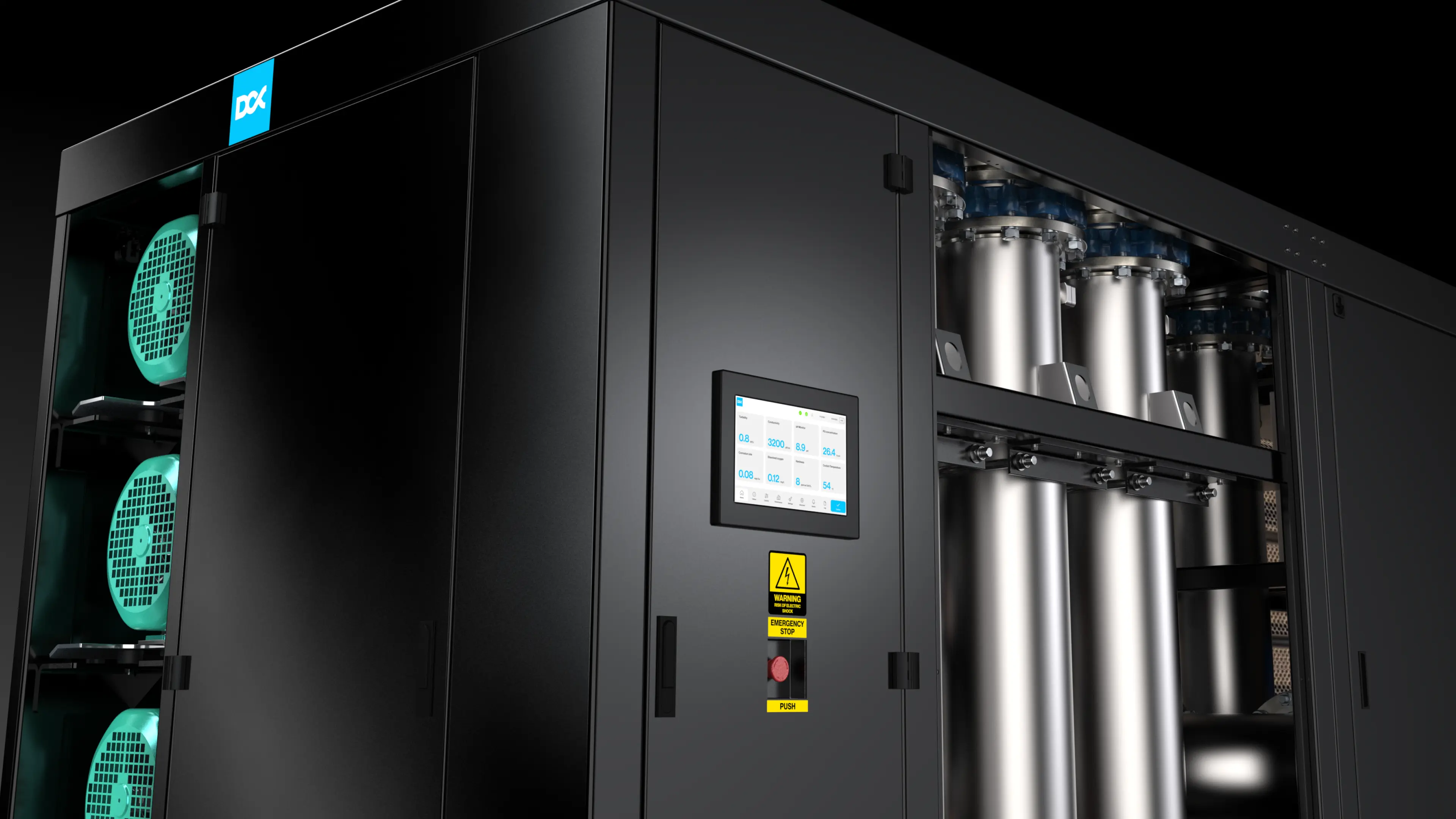
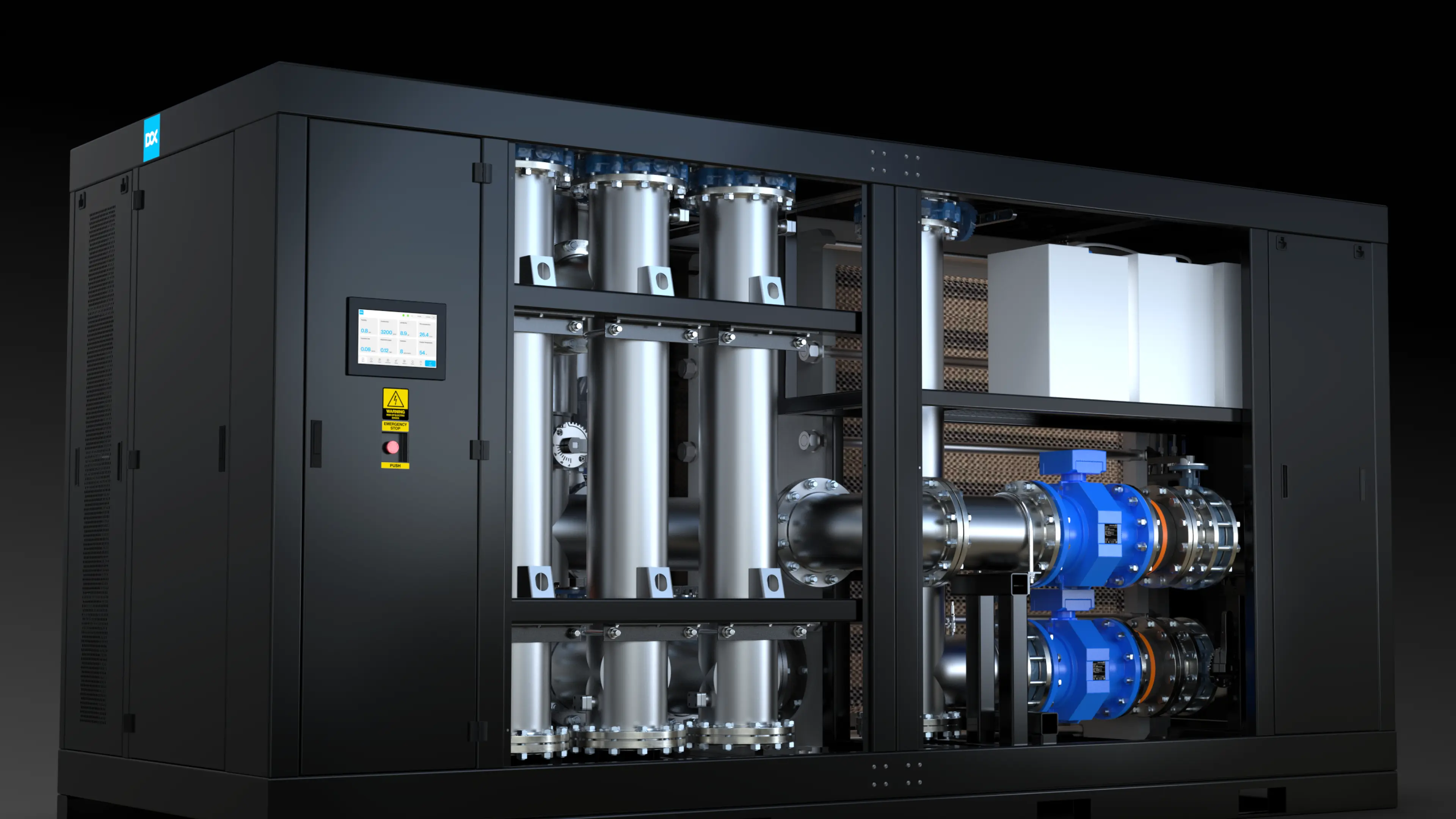
The operational "heart" is the CDU, which regulates flow and temperatures and typically includes a heat exchanger and redundant pumps. CDUs are deployed as in-rack, in-row, or facility-level units, depending on the required capacity and scalability.
The future of Direct-to-Chip cooling
By 2030, AI-oriented semiconductors are projected to account for a significantly larger share of global data center chip spending, as new AI processors increasingly adopt chiplet-based designs. AI chips are projected to grow their total revenue share from 20% to 50%. This evolution is not only about higher performance, but it also reshapes the thermal reality inside the server.
This shift is expected to create an approximately $180 billion data center semiconductor market, driven by AI GPUs priced around $15,000-$30,000 per unit, an order of magnitude above traditional CPUs at roughly $1,200. The infrastructure impact is equally structural: average rack density is projected to triple to ~45 kW, and liquid cooling adoption in new facilities could reach around 80%, making advanced cooling a baseline design requirement.
At the same time, custom silicon is expected to capture ~15% market share, with hyperscalers increasingly developing their own processors to optimize performance for specific workloads. Longer term, emerging approaches such as neuromorphic computing may improve inference efficiency, but the near-term direction is unmistakable: higher compute concentration, tighter thermal margins, and more hotspot-driven server designs.
That is why Direct-to-Chip cooling is turning into a baseline technology for AI-ready data centers: it removes heat exactly where it is generated (CPU/GPU), stabilizes operating conditions for next-generation platforms, and enables rack densities and deployment velocity that air-based architectures struggle to sustain.
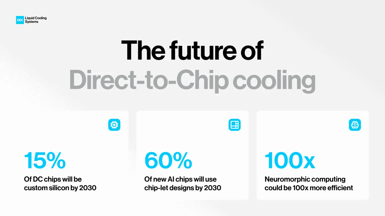
Source: JLL Research 2026 Global Data Center Outlook
About DCX Liquid Cooling Systems
DCX Liquid Cooling Systems is a premier global manufacturer offering an extensive range of sustainable liquid cooling solutions, including both Direct Liquid Cooling and Immersion Cooling technologies. The company designs & manufactures Server Immersion Enclosures, Coolant Distribution Units (CDUs) including Hyperscale FDU (Facility sized CDU) system, CPU and GPU coldplates, manifolds and other components of liquid cooling system. DCX delivers Hydro & Immersion Containers and facility-based systems. DCX supplies Immersion Optimised Dry Coolers and a Thermasafe Dielectric Engineered Fluids. Hardware solutions are complemented with liquid cooled data hall design and implementation services, making DCX the first choice for liquid cooling systems’ supplier.
For More Information,
Please Contact
Jacek Dolny
Head of Marketing
jacek.dolny@dcx.eu

We Will Guide You the Whole Time
Everything starts with conversation. Trust us with your project and get us to work on your idea
Invite Us to Your Project
We support both small entities and large enterprises. Initial system design – free of charge.

Let’s Chat with Us
If you have a liquid cooling or heat reuse project – we are yours to talk. Free of charge.

Get the Support
A comprehensive remote, and on-site service. Included with every system we deliver.

Liquid Cooling Explained
Discover the future of data center cooling through a series of short, expert-led videos. Our CTO, Maciek Szadkowski, answers the most important questions, debunks common myths, and reveals what really matters when it comes to modern liquid cooling systems.
Watch the Series
Tell Us About Your Project
The more you tell us up front, the faster we can come back with a real design rather than a brochure. Where possible, include:
- IT load: target capacity in MW, and rack density in kW
- Hardware: GPU or accelerator platform, rack format (19", 21", ORV3), cold plate or immersion
- Loop conditions: available facility water temperature and flow, or "not decided yet"
- Heat rejection: dry coolers, chilled water, district heating, or open
- Site: city and country, plus design ambient temperature
- Timeline: target energisation date and whether this is new build or retrofit
Contact