Warsaw, Poland, May 15, 2026
Liquid cooling reinvented: why the FDU is the new standard in AI data centers
The rapid advancement of generative artificial intelligence has triggered a global technological arms race. Next-generation AI models not only learn faster and process increasingly large datasets, but most critically, demand unprecedented levels of compute power. This shift is placing immense pressure on data centers, accelerating the adoption of liquid cooling solutions and transforming the design of AI infrastructure to support high-density computing at scale.
This shift is accompanied by a sharp increase in power density – not incremental, but exponential. In modern AI clusters, 60-120 kW per server rack has become the new standard, with early deployments already exceeding 200 kW per rack. According to the latest hardware vendor roadmaps, by 2027, single rack deployments may require up to 600 kW of cooling capacity.
In this context, traditional liquid cooling systems based on distributed, in-row Coolant Distribution Units (CDUs) are reaching their limits. Each in-row CDU module typically serves a small group of racks, requires white space floor allocation, demands independent maintenance, and adds significant installation and operational overhead. When scaled to support tens of megawatts of IT load, this architecture becomes inefficient, costly, and increasingly difficult to maintain.
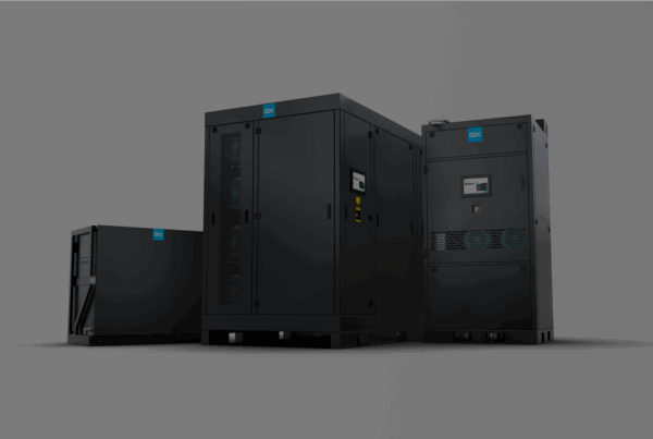
To address these challenges, we propose a new cooling topology – centralized, resilient, and purpose-built for the needs of large-scale AI deployments. The Facility Distribution Unit (FDU) is a 5-megawatt liquid cooling system installed outside the white space, engineered to serve entire data halls. It replaces dozens of scattered CDUs, simplifies cooling infrastructure, and significantly reduces the risk of failure near mission-critical IT hardware.
The era of extreme density in data centers: AI is the main disruptor
Over the past decade, data centers have undergone a rapid transformation driven by artificial intelligence, high-performance computing (HPC), and the surging power consumption of modern CPUs and GPUs. In particular, generative AI and large language models (LLMs) have introduced entirely new demands for IT infrastructure.
Back in 2010, a typical server rack was designed to support 5-10 kW of power density, and the thermal design power (TDP) of processors rarely exceeded 150-200 W. At the time, legacy cooling topologies based on multiple 1 MW coolant distribution units (CDUs) installed directly in the white space were sufficient to meet infrastructure requirements.
Today, the landscape has fundamentally changed. Virtualization, hyperscalers and now AI workloads have pushed those previously known limits. In 2025, some data centers are already cooling 240 kW per rack, driven by dense GPU clusters powering large-scale AI workloads. And this is just the beginning, as NVIDIA’s roadmap predicts racks drawing up to 600 kW by 2027, which is a 10 × leap over today’s high end and an astonishing 100× increase over the classic enterprise rack of the 2010s.

Figure 1. Rising rack densities
What technological and operational trends explain this growth in rack density?
- Massive AI models need thousands of GPUs per deployment.
- Liquid cooling technologies like Direct-To-Chip and built-in heat exchangers are unlocking higher thermal capacities.
- Space and energy efficiency demands push operators to get more compute per square foot, as higher density is the only solution.
| Year | Typical CPU thermal design power (TDP) | Typical GPU thermal design power (TDP) | Average rack power density | Peak rack density (AI/HPC) |
|---|---|---|---|---|
| 2010 | 130-180 W | 200-250 W | 5-10 kW | <10 kW |
| 2025 | 250-600 W | 700-1200 W | 8-17 kW | 60-120 kW (sometimes reaching 200 kW) |
| 2027 | 600-800 W | 1200-1600+ W | 20-30 kW | 150-200+ kW (NVIDIA forecasts up to 600 kW) |
Table 1. A comparison of industry evolution – past, present, and future.
The increasing demand for power and higher compute density is significantly changing the requirements for cooling infrastructure in data centers. Modern data centers cannot be designed according to outdated standards of 5-10 kW per rack. Instead, they must be future-ready, designed for peak rack power densities of 200-600 kW, as required by modern AI and high-performance computing workloads.
This change necessitates a fundamentally new approach that provides greater cooling power, wider reach, and minimized operational risks. That’s why solutions like our DCX Facility Distribution Unit, which was designed to deliver reliable, large-scale liquid cooling, are becoming necessities now and in the future. One unit can efficiently handle entire AI halls with ultrahigh densities, while staying compact and easy to maintain.
Legacy cooling can’t keep up with AI: cost and risk breakdown
Traditional liquid cooling systems that use distributed Coolant Distribution Units (CDUs) installed in the white space were originally designed to handle rack power densities between 5-10 kW. However, with the rise of artificial intelligence and the growing density of high-performance computing (HPC) clusters, the limitations of these systems have become more evident, both technically and economically.
Key limitations and risks of traditional liquid cooling architectures:
- Infrastructure Complexity and Cost:
Each Cooling Distribution Unit (CDU) requires separate installation, connections, leak testing, and ongoing maintenance. In environments with a large number of racks, the components increase rapidly, leading to higher capital expenditures (CAPEX) and operational expenditures (OPEX). - High Failure Risk:
Every additional connection, valve, or pump introduces a potential point of failure. In AI data centers, where a single rack can represent millions of dollars in compute value, the failure of a single cooling unit can result in downtime across multiple critical systems. - Lack of Flexibility and Scalability:
Distributed CDU loops are typically assigned to fixed rack groups. This can lead to stranded capacity – unused cooling potential that is difficult to reallocate or reconfigure in rapidly scaling AI environments. - Insufficient Performance at High Densities:
A typical in-row CDU can support 5-10 racks, with a total capacity of 500-800 kW (80-100 kW per rack). However, at densities of 200 kW per rack, these systems become inadequate and would require an impractically large number of CDUs to meet cooling demands. - White Space Occupancy:
In-row CDUs physically compete for space with server hardware. This not only reduces the usable IT footprint but also increases operational risk by placing mechanical infrastructure near high-value compute nodes.
| Area | Risk | Financial Impact |
|---|---|---|
| Number of CDUs | More units = more potential failure points | Higher CAPEX + increased service cost |
| Localized Failures | A single malfunction can disable multiple server racks | Downtime |
| Maintenance | Multiple maintenance cycles across components | Operational time and cost burden |
| Lack of Modularity | No adaptability to future AI rack densities | Infrastructure reconfiguration costs |
| White Space Utilization | CDUs occupy valuable IT floor space | Lost compute capacity |
Table 2. Risk-to-cost mapping in traditional cooling architectures
Why should cooling infrastructure be moved outside the white space in data centers?
In traditional liquid cooling systems often referred to as “legacy architecture” – Coolant Distribution Units (CDUs) are placed directly within the IT space. While this method was adequate for moderate power densities, the rise of artificial intelligence and high-performance computing has revealed its shortcomings, such as the risk of leaks, complicated maintenance, and inefficient use of valuable IT space.
Modern cooling architecture takes a different approach by relocating essential cooling infrastructure outside the IT area. This change offers a variety of practical advantages:
- Fewer units, greater capacity:
Instead of installing five separate 1 MW CDUs, a single 5 MW Facility Distribution Unit (FDU) can support the entire data hall, simplifying the system and reducing hardware clutter. - Leak risk mitigation:
Every pipe fitting and gasket introduces a potential failure point. A coolant leak inside the white space can short-circuit components, damage GPUs, and cause extended downtime. Moving CDUs outside drastically reduces the number of joints in the IT zone, significantly lowering incident risk. - Simplified maintenance and serviceability:
In-row CDUs complicate access and servicing – hoses and pipework often obstruct service corridors. By contrast, an FDU placed in a service corridor or outside the white space is easier to maintain, serviceable without entering critical areas, and doesn’t interfere with IT operations. - Recovered white space:
Traditional CDU placement consumes valuable floor area next to server racks, reducing available rack space and limiting future expansion. Removing CDUs from the white space frees up capacity for additional racks and allows higher equipment density, maximizing the value of the data center footprint.
What is an FDU and why it redefines liquid cooling infrastructure
Facility Distribution Unit (FDU) is a centralized coolant distribution unit used in direct liquid cooling systems for large-scale server clusters, including GPU-intensive environments. Unlike traditional Coolant Distribution Units (CDUs), which are typically installed locally in IT rows, the FDU is deployed outside the white space – either in a technical corridor or even outside. This relocation fundamentally changes both the cooling architecture and the physical design of data centers.
The new cooling topology based on FDU eliminates the legacy model of numerous distributed small cooling loops (each with its own CDU, pump, and heat exchanger) and replaces them with a single, high-capacity unit supporting the entire IT zone through centralized supply and return loops. This significantly reduces the number of critical components placed directly near the IT hardware.
With high-pump head capabilities (loop reach exceeding 50 m), FDUs allow flexible placement of high-density racks based on power availability, structural constraints, or cabling, rather than proximity to cooling units. The use of standardized loop topology ensures repeatability across deployments: whether the system supports 20 or 200 racks, the piping layout, controls, and integration logic remain consistent. This reduces engineering effort, commissioning time, and the likelihood of configuration errors.
From a logical architecture standpoint, the FDU becomes the central node of the thermal cooling system, bridging the chilled water source with the downstream distribution network that feeds manifolds and server-side cold plates. As a result, local CDUs become obsolete – their function is taken over by a centralized FDU offering greater capacity, longer reach, and full diagnostic control via the facility management layer.

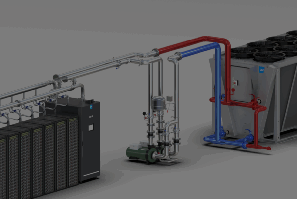
Figure 2. New topology standard for modern data centers – 5MW FDU
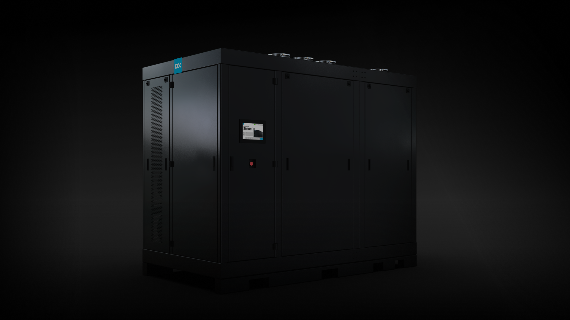
Key technical features of the 5 MW FDU unit:
- Designed for full data halls and large-scale AI deployments:
The 5 MW FDU provides the highest heat transfer capacity per unit available on the market, eliminating the need for dozens of in-row CDUs in high-density deployments. - Supports up to 60 AI racks at 80 kW each:
Capable of supporting to 60 AI racks, each consuming around 80 kW and equipped with NVIDIA H100 GPUs or equivalent, enabling seamless operation of over 1,000 servers. - Compact footprint with high output capacity:
At just 3.0 m (L) × 1.5 m (W) × 2.3 m (H), the unit delivers unmatched capacity per square meter, ideal for space-constrained facilities. - Smart 37 kW inverter system with predictive diagnostics:
Embedded accelerometers, pressure and incline sensors feed a remote analytics platform. It enables early detection of operational anomalies, such as: dirty filters, sand fouling and debris buildup, pump wear or impeller damage, rising system friction or degraded hydraulic performance. - High pump head and multi-pump redundancy (N+1):
Equipped with four industrial-grade pumps, each capable of 8,000 L/min, with peak burst performance up to 10,666 L/min. The unit includes multiple built in pumps that delivers twice the power of standard high-capacity CDUs, along with N+1 redundancy pumps. This makes it perfectly suited for large-scale secondary loop configurations that require high reliability. - Redundant electronic control panel with LCD HMI:
Dual-path logic with redundant PLC controllers ensures full local control and immediate system response in case of alerts or anomalies. The intuitive, crystal-clear HMI interface gives operators real-time visibility and 24/7 operational control. - Integrated coolant conditioning system:
Maintains coolant purity without the performance penalties associated with glycol-based fluids such as PG25, which can cause up to a 20% efficiency loss. - Customizable heat exchanger:
The FDU contains a single, high-capacity heat exchanger that can be resized by removing or adding plates to match project-specific requirements. - Full compliance with Tier 3 Uptime Institute requirements:
FDUs provide higher fault tolerance compared to legacy systems. With an N+1 redundant configuration: additional pumps and components – they continue operation during maintenance or a single-point failure. Centralized monitoring and onboard sensors also enable proactive diagnostics before issues impact IT hardware. - Future-proof scalability:
Computing power demand from next-gen AI workloads is inherently unpredictable – models evolve faster than infrastructure investment cycles. FDU based cooling offers an adaptive, scalable architecture capable of supporting rapid increases in rack power density without requiring complete redesigns.
Topology of the 5 MW FDU
In the FDU model, the most critical changes involve the method of coolant distribution and the physical location of key components. The Facility Distribution Unit integrates the entire pumping system, heat exchangers, fluid conditioning module, and operational sensors into a single unit. Importantly, all of these components are located outside the white space.Instead of deploying ad hoc CDU units inside IT racks, the system designer has access to one centralized distribution node, from which only two main loops: supply and return – are routed and then branched locally.
One key advantage is the complete separation of circuits – the coolant on the facility water side (FWS) never mixes with the server loop. Coolant integrity is ensured by an integrated fluid conditioning system, including filtration, air and particle separation, and conductivity control. Moreover, FDU pumps deliver twice the pressure head of standard CDU units, enabling reliable supply over longer pipe runs without compromising performance.
As a result, this cooling architecture not only meets today’s thermal demands (60-120 kW per rack), but is also prepared for future density levels reaching 200-600 kW per rack. The FDU becomes not just an infrastructure component, but a cornerstone of modern data center design strategy.

Figure 3. Previous topology featuring the CDU located in the white space.

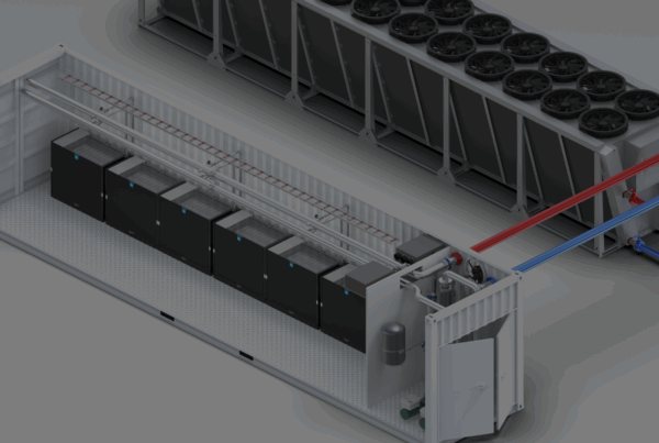
Figure 4. New topology – FDU outside the white space.
The following comparison outlines the key differences between the traditional CDU topology and the modern AI-ready FDU-based architecture.

Figure 5. Comparison of cooling topologies
Why the 5 MW FDU is the “sweet spot” for AI data center liquid cooling?
As compute densities and cooling demands continue to surge, data center architects require a solution that is modular, energy-efficient, and tailored to the real-world needs of modern AI clusters. The 5 MW Facility Distribution Unit (FDU) emerges as an optimal choice for several key reasons:
- Natural fit for AI clusters:
The 5 MW FDU is purpose-built for standard AI cluster configurations consisting of 40-60 high-density racks populated with high-performance GPUs, for example, 1024 NVIDIA H100 accelerators. A single FDU can effectively cool such a GPU cluster without overprovisioning or underprovisioning, making it a natural planning unit for hyperscale and AI colocation environments. - Optimal cost-efficiency:
Take a 10 MW compute hall as an example: A legacy architecture using 24 distributed CDU units would incur a CAPEX of approximately $3.12 million. Replacing them with three FDUs (2 active + 1 standby) reduces infrastructure cost to just $0.97 million – over $2.2 million in savings, or nearly 70% lower capital expenditure on the cooling system alone. - Reduced operational energy consumption:
Cooling systems play a critical role in AI workloads where Power Usage Effectiveness (PUE) is under scrutiny. FDU-based architectures consume ~28% less auxiliary energy (for pumps, fans, etc.), translating to a power draw reduction of roughly 86 kW. This contributes directly to lower electricity bills and improved energy efficiency. - Scalable modularity in 5-15 MW blocks:
The 5 MW FDU represents a practical unit of modular expansion, allowing data center infrastructure to be planned in scalable building blocks. This enables phased investments and incremental capacity increases (e.g., 5, 10, 15 MW), aligned with actual AI growth. FDUs also support N+1 and 2N redundancy schemes, facilitating Tier III compliance and streamlined certification

Figure 6. Cost and energy comparison: legacy in-row cooling vs. modern 5 MW FDU for a 10 MW hall.