Warsaw, Poland, May 29, 2026
Facility vs.Technology cooling systems: what primary and secondary separation, really, means for AI?
Behind every high-density data center lies a carefully structured cooling architecture. Rather than relying on a single circulation path, modern facilities separate heat transport into two interconnected loops: the Facility Water System (FWS) and the Technology Cooling System (TCS). The two-loop architecture is based on a simple principle: separating facility-scale heat transport from IT-level cooling.
FWS distributes heat throughout the building and interfaces with chillers, cooling towers, and heat-reuse systems. TCS works at the IT level, delivering coolant from the Coolant Distribution Unit (CDU) to cold plates and removing heat directly from CPUs and GPUs. At the center of this architecture, the CDU acts as the thermal and hydraulic interface, connecting both loops through a liquid-to-liquid heat exchanger.
This FWS and TCS topology enables precise control of coolant conditions at the server level while maintaining stable heat transport across the entire facility. Understanding how and why these two systems interact is key to explaining the rapid shift toward liquid cooling architectures.
The logic behind Facility and Technology Cooling Systems
To ensure stability and scalability, modern data centers employ two distinct cooling domains: the Facility Water System (FWS) and the Technology Cooling System (TCS).
Facility Water System (FWS) piping carries either chilled water from cooling plants or warm water destined for dry coolers, depending on the site design. It serves as the bridge between the building’s central cooling resources and the server-side systems, ensuring that heat generated in the racks can be removed from the facility with minimal energy loss.
Because of its role as the backbone of liquid cooling infrastructure, FWS piping must be engineered for durability, leak protection, and long-term stability. It is built to handle varying operating conditions, seasonal temperaturę changes, and continuous 24/7 operation without compromising performance. In essence, FWS piping is what makes datacenter-scale liquid cooling possible, providing the dependable, high-capacity circulation needed to keep advanced IT workloads running efficiently.
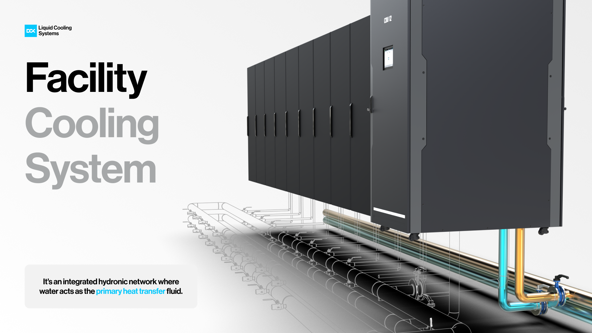
Figure 1. The Facility Water System (FWS)
Technology Cooling System (TCS) piping connects the key components of a liquid-cooled system, including cold plates, Coolant Distribution Units (CDUs), and heat rejection equipment such as dry coolers. These pipes transport coolant throughout the loop, efficiently and securely removing heat from high-performance IT loads.
Each system must be precisely engineered to accommodate flow rate, operating pressure, material compatibility, and thermal expansion, while ensuring safe integration with the facility’s cooling fluids and environmental conditions. DCX’s tailored approach guarantees a robust and scalable piping backbone for any liquid cooling deployment.
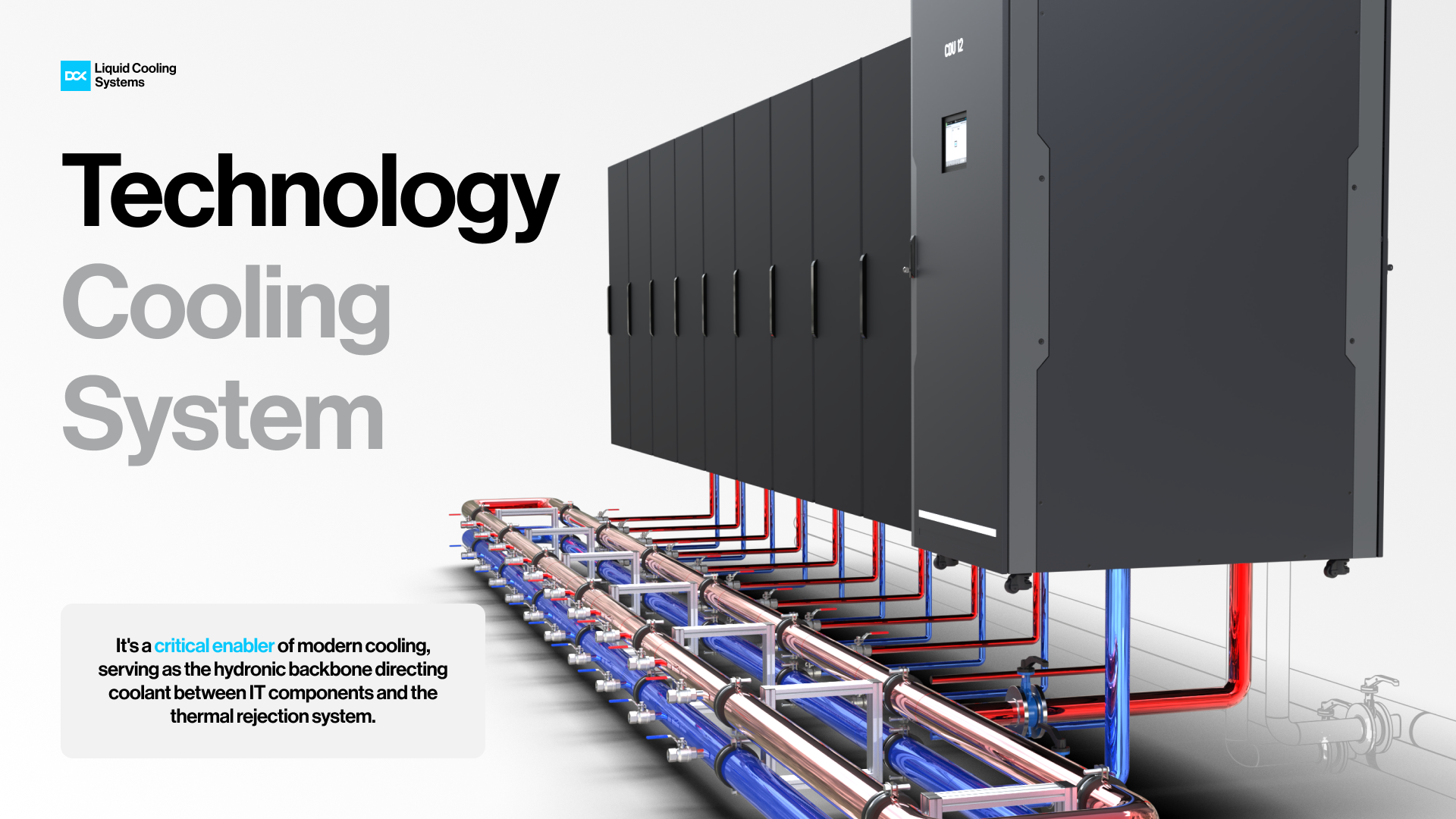
Figure 2. Technology Cooling System (TCS)
The following comparison outlines the key differences between the Facility Water System (FWS) and Thermal Cooling System (TCS)
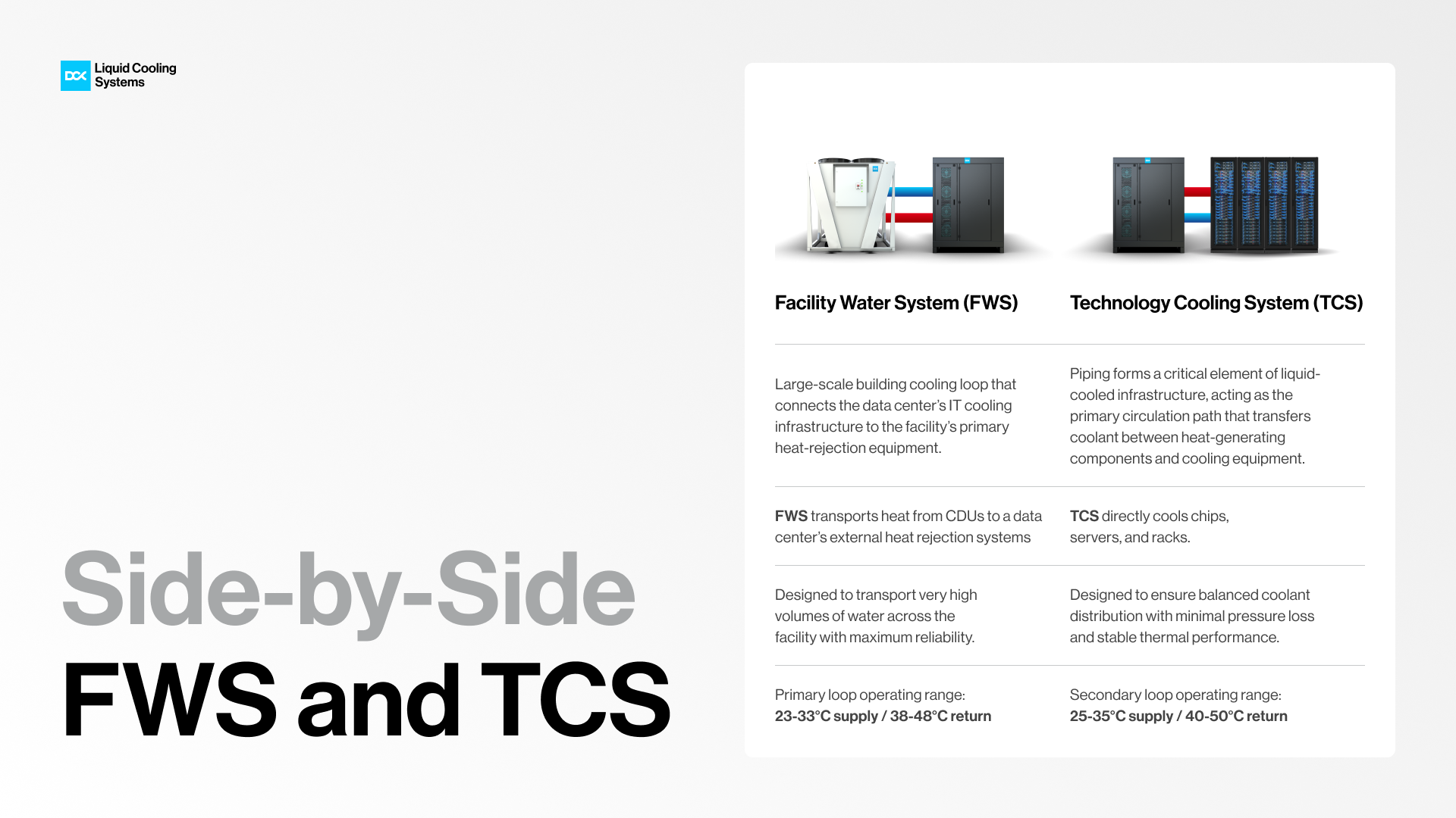
Figure 3. Comparison of FWS and TCS piping*
*Typical operating conditions based on a 2°C approach temperature and ΔT up to 15°C.
In AI and HPC environments, data center operators are beginning to face a new challenge: traditional primary and secondary cooling loops may no longer be sufficient to efficiently remove heat directly at the rack level. In such scenarios, there is also a supplementary cooling approach based on a Chilled Water System (CWS), where Rear Door Heat Exchangers (RDHX) are integrated directly at the rack level to remove heat close to the source and support high-density IT environments.
The primary operating principle of the CWS loop is the removal of heat generated by the servers through heat exchangers integrated into the RDHX units. The CWS loop may also support Computer Room Air Handler (CRAH) units, enabling additional heat removal at the room level and helping maintain stable ambient thermal conditions within the data center. The system supplies chilled water to the RDHX units installed on the racks, while hot exhaust air discharged from the servers passes through the integrated heat exchanger surface. During this process, thermal energy is transferred from the air stream to the chilled water circulating within the CWS loop. The heated water is then returned to the facility cooling infrastructure (typically a chiller system), where the heat is rejected, and the water is cooled before being recirculated back to the RDHX units.
Typical operating temperature ranges within the CWS loop may vary depending on the cooling architecture, rack density, and chiller configuration.
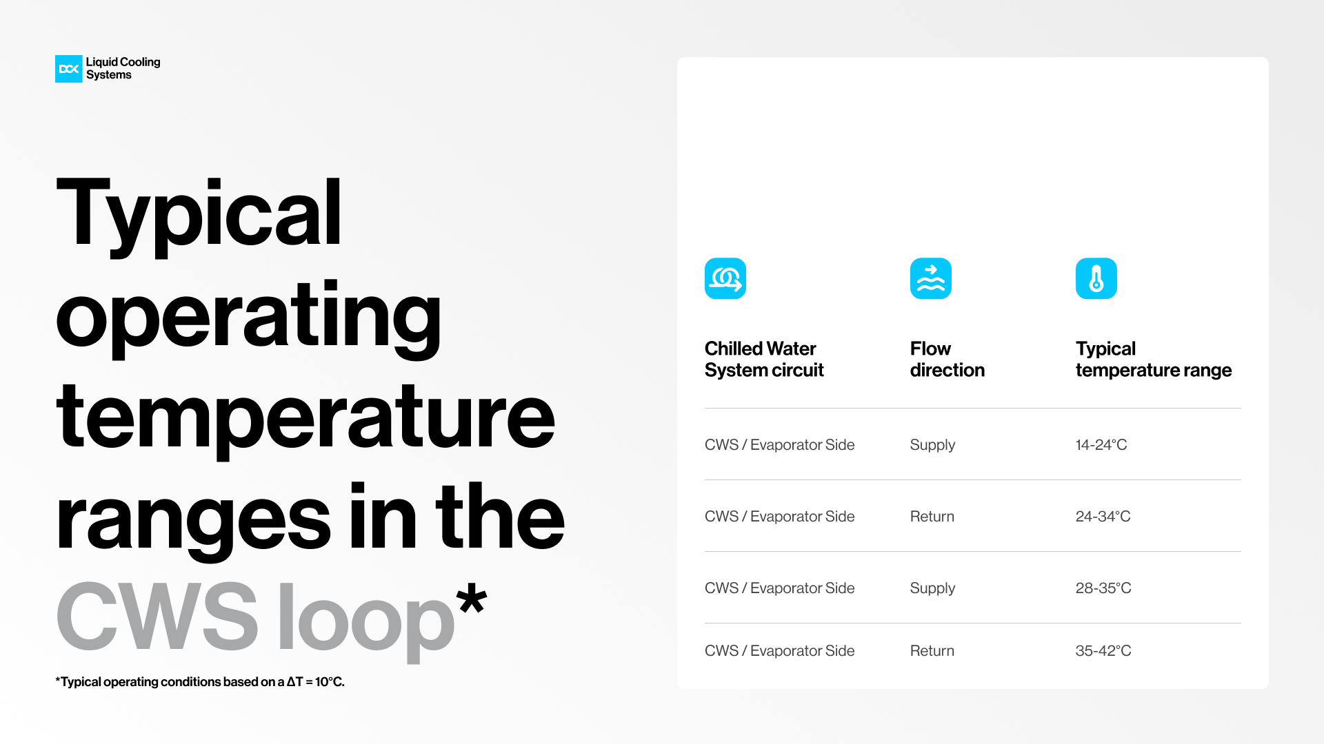
Table 1. Typical operating temperature ranges in the CWS loop*
However, introducing an additional cooling loop is not simply an extension of the existing infrastructure. It becomes a broader facility-level engineering consideration that affects the overall cooling architecture of the data center. Operators therefore need to start considering early in the design phase how a third loop would integrate with the existing cooling plant, including aspects such as hydraulic separation, pumping capacity, redundancy strategy, heat rejection capability, and future scalability.
The architecture of modern liquid cooling infrastructure
Modern liquid-cooled data centers are organized around a two loop cooling architecture in which the primary and secondary cooling loops operate as interconnected but hydraulically separated domains.
The Facility Water System functions as the primary loop, responsible for building-level heat transport, while the Technology Cooling System operates as the secondary loop, managing heat removal directly within the IT environment. The coordination between these two layers forms the backbone of modern liquid cooling infrastructure.
At the center of this architecture is the Coolant Distribution Unit (CDU), which acts as the thermal and hydraulic interface between the primary and secondary loops. Inside the CDU, a liquid-to-liquid heat exchanger transfers thermal energy from the secondary loop (TCS) to the primary loop (FWS) while keeping both circuits physically separated. This separation allows each loop to operate under its own hydraulic conditions, temperatures, and water quality requirements without compromising system reliability.
From the CDU, coolant circulates through the secondary loop toward rack manifolds and server-level heat exchangers, where heat generated by high-density computing components is captured and transported back to the unit. The extracted heat is then transferred to the primary loop, which carries it toward the site’s heat-rejection infrastructure.
This primary and secondary topology enables precise thermal control at the rack level while maintaining stable, high-capacity heat transport across the facility. By separating building-scale heat management from the sensitive IT cooling environment, the architecture supports scalable deployments, operational flexibility, and improved reliability in modern high-density data centers.
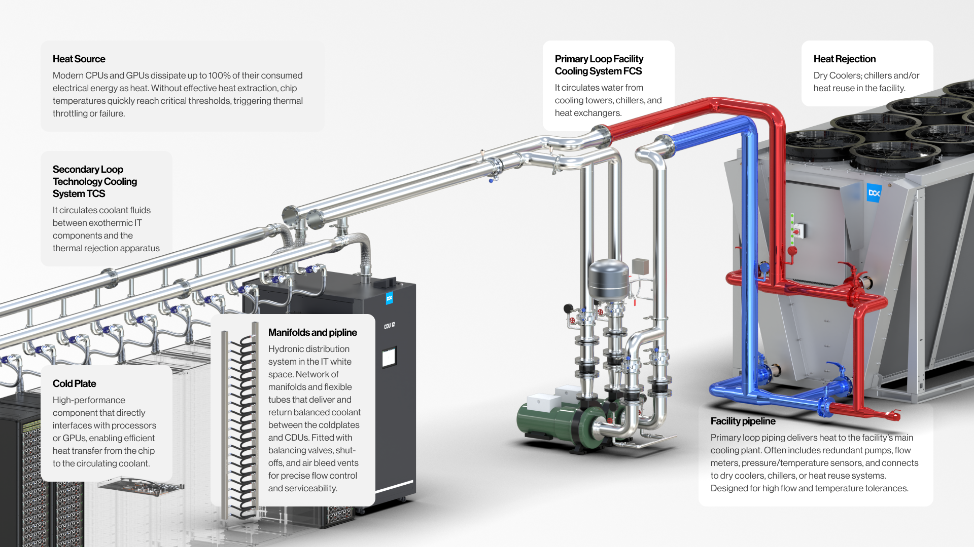
Figure 4. Facility and Technology Cooling Systems topology.
Scaling the architecture
AI clusters are scaling to hundreds of kilowatts per rack and into multi-megawatt cooling domains, the same separation logic between the Facility Water System (FWS) and the Technology Cooling System (TCS) must also scale at the infrastructure level.
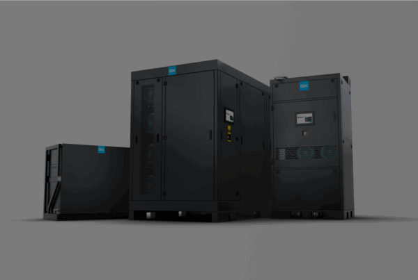
To support these environments, DCX developed Facility Distribution Units (FDUs), available in both 5 MW and 8 MW configurations. The FDU is a hyperscale cooling interface designed to manage high-capacity thermal transport between the facility’s cooling infrastructure and multiple technology cooling loops.
The FDU integrates a dual-loop CDU architecture: the Facility Water System (FWS) and the Technology Cooling System (TCS). Inside the unit, a dual-loop CDU architecture hydraulically separates the primary facility loop from the secondary technology loop while enabling controlled heat transfer between them through liquid-to-liquid heat exchange. This configuration allows the TCS circuit supplying cold plates and rack manifolds to operate at reduced and tightly controlled pressure levels required by sensitive IT equipment, while the FWS loop maintains the high flow rates necessary to transport heat toward facility-level heat rejection systems.
To maintain stable operation in high-density environments, the FDU incorporates dew-point monitoring and condensation control mechanisms that ensure the coolant temperature within the Technology Cooling System remains above the ambient dew point, preventing condensation inside IT hardware. At the same time, strict hydraulic and fluid separation between the primary and secondary circuits allows each loop to maintain independent coolant chemistry and water quality parameters. This separation protects microchannel cold plates and server cooling components from contamination originating on the facility side while improving long-term operational reliability.
The system also provides flexible hydraulic integration through configurable primary (FWS) and secondary (TCS) supply and return ports located both at the top and bottom of the unit. This allows the FDU to be connected from multiple directions, simplifying integration with existing piping layouts and supporting scalable deployments or retrofits in large data center facilities.
Benefits of separating Facility and Technology Cooling Systems
The Cooling Distribution Unit (CDU) plays a crucial role in liquid cooling systems by hydraulically separating the two cooling loops. In DCX CDUs, the separation between the Facility Cooling System and the Technology Cooling System ensures not only thermal efficiency but also enhances system reliability, operational safety, and long-term fluid stability. This separation enables:
- Support for diverse coolant media in the TCS loop (e.g., up to 50% glycol blends), increasing deployment flexibility across different climates and infrastructure conditions.
- Prevention of condensation within IT equipment by maintaining TCS fluid temperatures above the local dew point.
- Elimination of galvanic corrosion risk through material isolation between facility-side and server-side fluid paths.
- Precise control of coolant quality and chemistry, ensuring compatibility with sensitive internal server components and microchannel cold plates.
- Customizable coolant supply temperatures to IT loads, enabling optimization for varying rack power densities and thermal profiles.
- Reduced operating pressure on server cooling components, ensuring compliance with server manufacturer requirements and extending component lifespan.
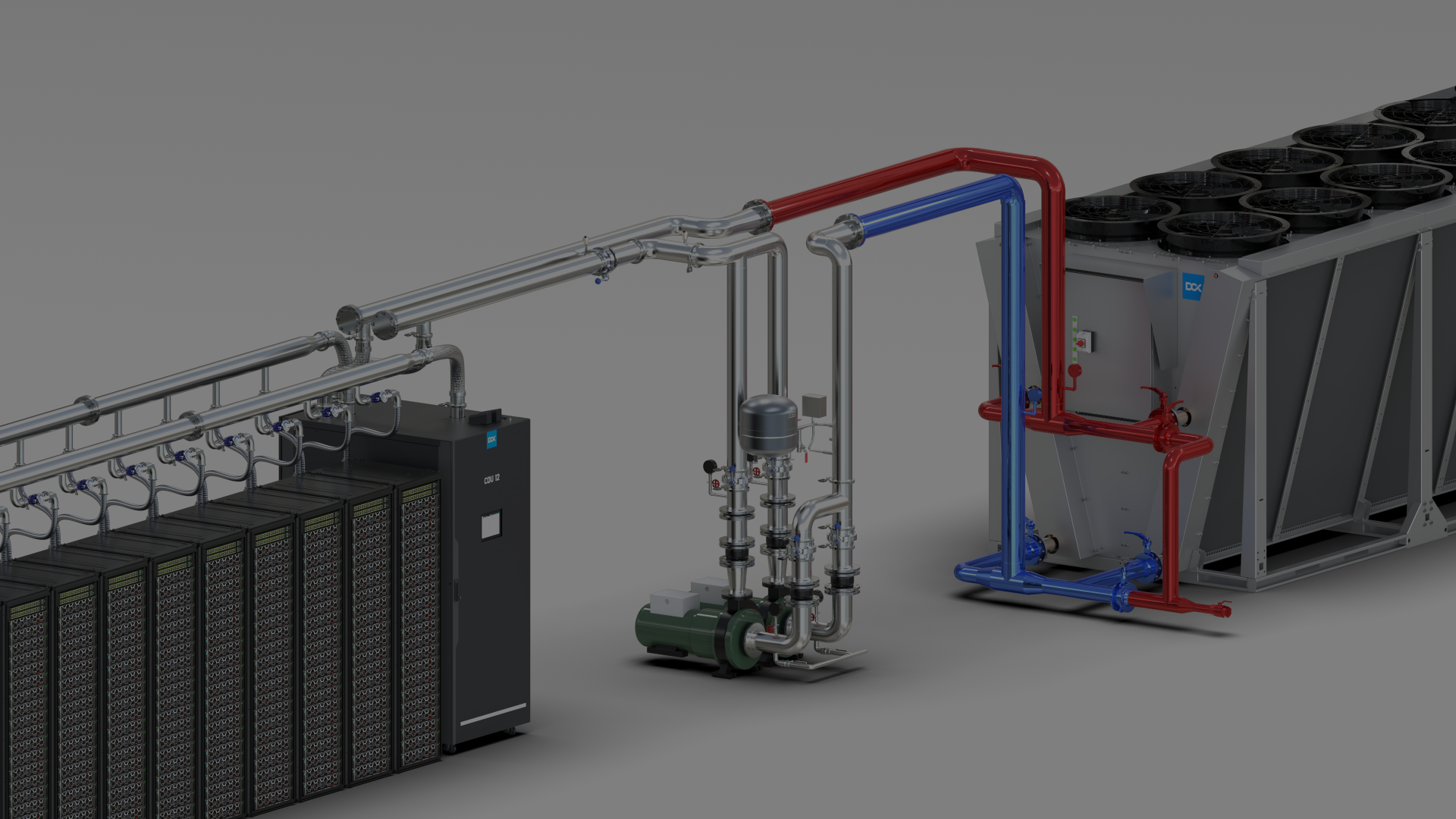
- Efficient heat transfer, a dedicated coolant loop, hydraulically separated from the facility water system, removes heat through red (hot) and blue (cold) pipelines, ensuring stable performance and system reliability.
Together, FWS and TCS separation establishes a stable, scalable, and energy-efficient foundation for next-generation data center infrastructure.
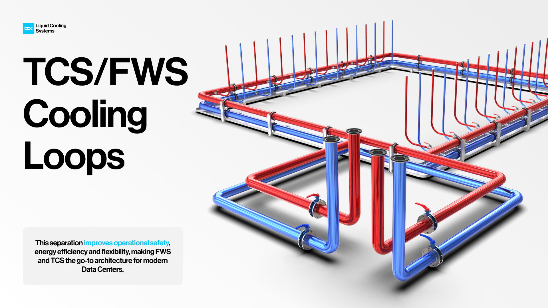
Figure 5. TCS and FWS cooling loops
DCX implementation of FWS and TCS cooling topology
DCX offers a modular liquid-cooling infrastructure designed to pre-engineer the separation of the Technology Cooling System and the Facility Water System. In cooling solutions such as Direct-to-Chip (DTC), the topology is split into two clearly separated circuits: the Facility Cooling System (FCS) primary loop and the Technology Cooling System (TCS) secondary loop. This division has become a standard approach in modern data center and high-density data hall design, because it separates the “building-side” heat rejection infrastructure from the tightly controlled technology loop that directly serves CPU/GPU cold plates.
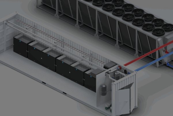
DCX implements this architecture through modular and factory-integrated solutions such as the DCX HYDRO, where containerized systems are engineered for direct-to-chip heat extraction, it ensures optimal thermal performance for even the most powerful ASIC miners. By efficiently managing heat at scale, HYDRO boosts system reliability, improves energy efficiency, and enables sustained high hashrate operation under continuous 24/7 workloads.
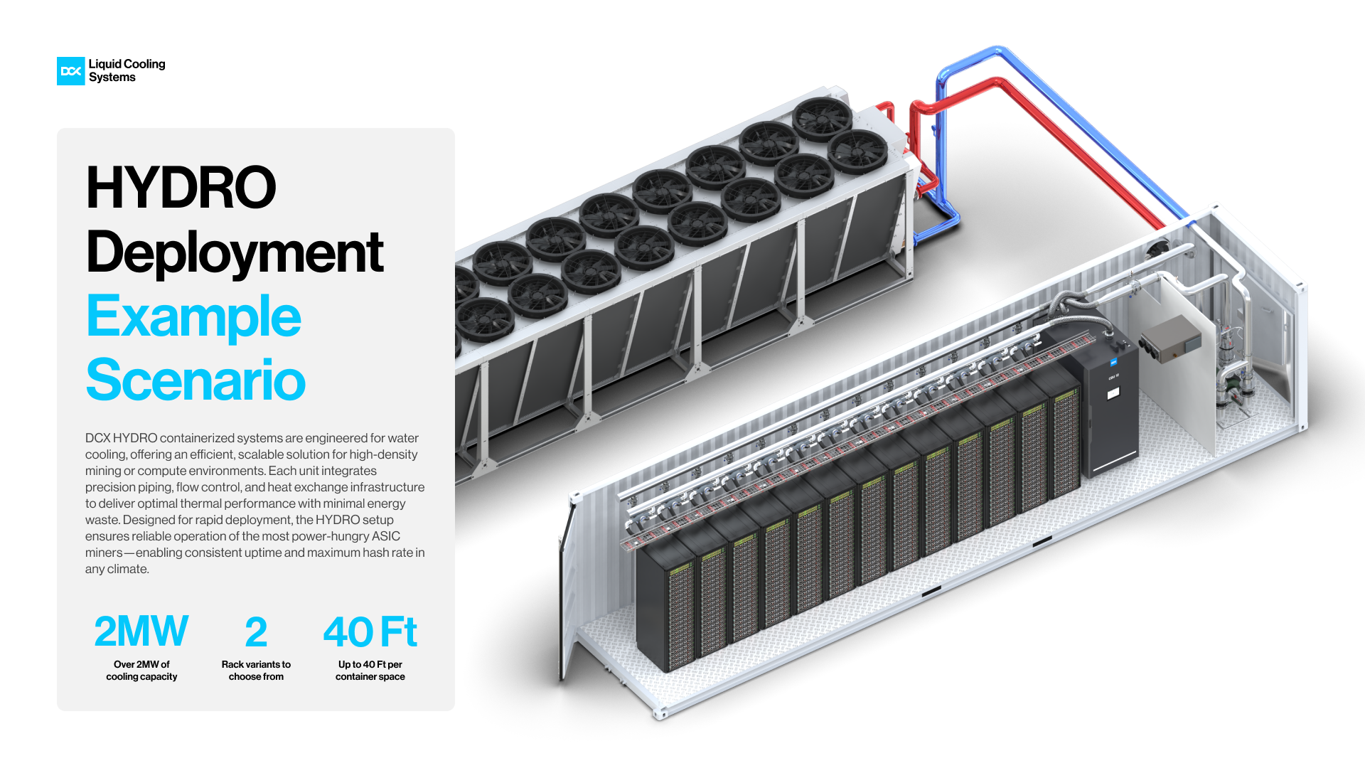
Figure 6. HYDRO deployment
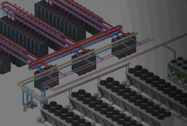
This approach is already being implemented in large-scale projects. DCX has been selected to deliver the Facility Water Systems (FWS) and Technology Cooling Systems (TCS) cooling loops for DataOne, Europe’s first gigascale AI hosting infrastructure data center in Grenoble, France. DCX is responsible for the full scope of the cooling infrastructure and will install and commission the complete heat rejection system. Such deployments demonstrate how the separation of facility and technology cooling domains can support scalable, high-density computing environments while maintaining operational stability and precise thermal control for advanced AI workloads.
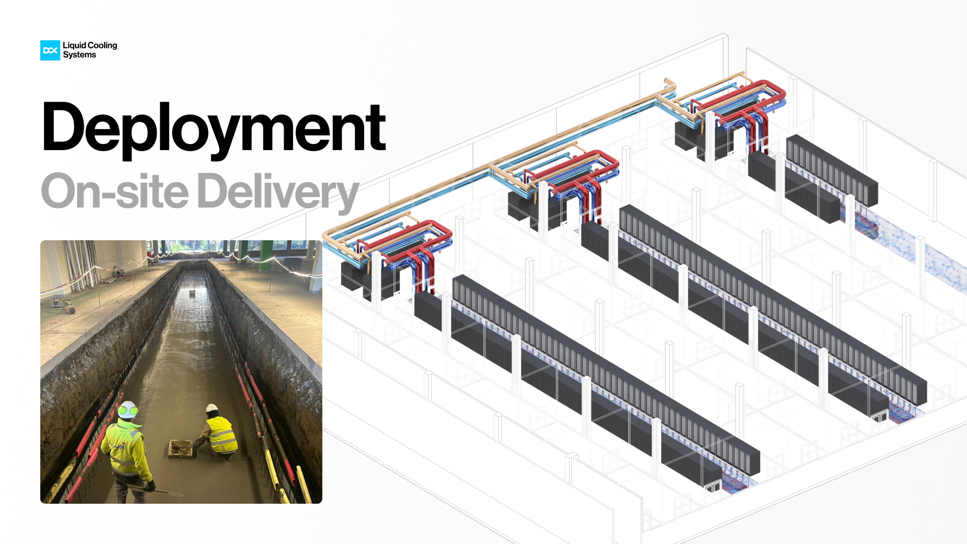
Figure 7. France deployment